Lecture
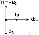
Take a coil with a ferromagnetic core and take out a separate element of the ohmic resistance of the winding as shown in Figure 1.
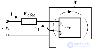
When an alternating voltage e c is applied to the coil, according to the law of electromagnetic induction, self-induced emf e L appears.
 (one)
(one) where ψ is flux linkage,
W is the number of turns in the winding,
Ф - the main magnetic flux. The scattering flow is neglected. The voltage applied to the coil and the induced emf are balanced. According to the second law Kirchhoff for the input circuit can be written:
e c + e L = i × R obm , (2)where R obm is the active resistance of the winding.
Since e L >> i × R vom , we neglect the voltage drop across the ohmic resistance, then e c ≈ –e L. If the mains voltage is harmonic, e c = E m cos ω t , then:
 (3)
(3) We find from this formula the magnetic flux. To do this, transfer the number of turns in the winding to the left side, and the magnetic flux F to the right:
 (four)
 Now we take the indefinite integral of the right and left parts:
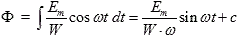 (five)
 Since the magnetic core is considered linear, only the harmonic current flows in the circuit and there is no permanent magnet or constant component of the magnetic flux, the integration constant c = 0. Then the fraction in front of the sine is the amplitude of the magnetic flux
 (6)
(6) where we express the amplitude of the input emf
E m = f m × W × ω (7)Its effective value is
 (eight)
 or
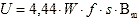 (9)
(9) Expression (9) is called the basic formula of the transformer EMF , which is valid only for harmonic voltage. In case of non-harmonic voltage, it is modified and the so-called form factor is introduced, which is equal to the ratio of the effective value to the average:
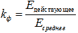 (ten)
(ten) Find the shape factor for the harmonic signal, with the average value found on the interval from 0 to π / 2
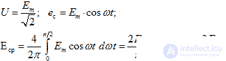 (eleven)
 Then the form factor is 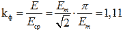 and the basic formula of transformer EMF takes the final form:
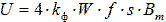 (12)
(12) If the signal is a sequence of rectangular pulses of the same duration (meander), then the amplitude, effective and average values for half the period are equal to each other and its k f = 1. You can find the shape factor for other signals. The basic formula of the transformer EMF will be valid.
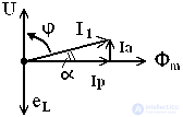
Construct a vector diagram of a coil with a ferromagnetic core. With a sinusoidal voltage at the terminals of the coil, its magnetic flux is also sinusoidal and lags in phase from the voltage by the angle π / 2 as shown in Figure 2.
In a lossless coil, the magnetizing current - reactive current ( I p ) coincides in phase with the magnetic flux Φ m . If there is a loss in the core ( P mag 0), then the angle of 90 ° - φ = α is the angle of the loss of magnetization reversal of the core. The active component of the current I and characterizes the losses in the magnetic circuit.

Comments
To leave a comment
Power supplies for electronic equipment
Terms: Power supplies for electronic equipment