
Industrial power supply modules Siemens SITOP Power. Lower right - PSU for AS-i interface
A secondary power supply is a device designed to provide power to an electrical electrical energy, while meeting the requirements of its parameters: voltage, current, etc., by converting energy to other power sources [1] . According to GOST R 52907-2008, the word “secondary” is omitted [2] .
The power supply may be integrated into the general circuit (usually in simple devices; or when even a slight voltage drop on the supply wires is unacceptable — for example, the computer’s motherboard has built-in voltage converters for powering the processor) made as a module (power supply, power supply .), or even located in a separate room (power supply shop).
Content
- 1 Tasks of the secondary power source
- 2 Transformer (mains) power supply
- 2.1 Dimensions of the transformer
- 2.2 Strengths and weaknesses
- 3 switching power supply
- 4 See also
- 5 Notes
- 6 Literature
- 7 References
Secondary power supply tasks
- Ensuring the transfer of power - the power source must ensure the transfer of a given power with the least losses and compliance with the specified characteristics at the output without harming oneself. Usually the power of the power source is taken with some margin.
- Conversion of the voltage form - the conversion of alternating voltage into a constant and vice versa, as well as frequency conversion, the formation of voltage pulses, etc. The conversion of an alternating voltage of industrial frequency into a constant frequency is most often necessary.
- Conversion of the voltage value - both increase and decrease. Often, a set of several voltages of various sizes is needed to power different circuits.
- Stabilization - voltage, current and other parameters at the output of the power source must lie within certain limits, depending on its purpose, when a large number of destabilizing factors influence: voltage changes at the input, load current, etc. Most often, voltage stabilization at the load is necessary. however, sometimes (for example, to charge batteries) current stabilization is necessary.
- Protection - voltage, or the load current in the event of a malfunction (for example, a short circuit) of any circuits may exceed the permissible limits and damage the appliance, or the power supply itself. Also, in many cases, protection against the passage of current through the wrong path is required: for example, the passage of current through the ground when a person or a foreign object touches live parts.
- Electrical isolation of circuits is one of the measures to protect against current flow in the wrong way.
- Adjustment - during operation it may be necessary to change any parameters to ensure proper operation of the appliance.
- Control - may include adjustment, on / off any circuits, or the power source in general. It can be either directly (using the controls on the device case) or remotely, as well as software (provision of on / off, adjustment at a specified time or with the occurrence of any events).
- Control - display of parameters at the input and at the output of the power source, on / off circuits, actuation of protection. It can also be direct or remote.
Most often, the secondary power sources are faced with the task of converting electric power from the industrial frequency network of alternating current (for example, in Russia - 220 V 50 Hz, in the USA - 120 V 60 Hz).
The two most typical designs are transformer and switching power supplies.
Transformer (mains) power supply
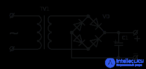
The scheme of the simplest transformer power supply without stabilization with a full-wave rectifier
The classic power supply is a transformer power supply unit. In general, it consists of a step-down transformer or autotransformer, whose primary winding is designed for mains voltage. Then a rectifier is installed that converts the AC voltage to a constant (pulsing unidirectional). In most cases, a rectifier consists of a single diode (half-wave rectifier) or four diodes that form a diode bridge (full-wave rectifier). Sometimes other circuits are used, for example, in voltage doubler rectifiers. After the rectifier filter is installed, smoothing oscillations (ripple). Usually it is just a large capacitor.
Also in the circuit can be installed high-frequency noise filters, bursts (varistors), short-circuit protection, voltage and current stabilizers.
Transformer Dimensions
There is a formula that is easily deduced from the basic laws of electrical engineering (and even Maxwell's equations):
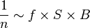
Where  - the number of turns per 1 volt (on the left side of the formula is the EMF of one turn, which is the derivative of the magnetic flux by the Maxwell equation, the flow is something in the form
  ,
,  - frequency of alternating current,
  - sectional area of the magnetic circuit,
  - induction of a magnetic field in it. The formula describes the amplitude rather than instantaneous value.
Magnitude in practice, it is limited from above by the occurrence of hysteresis in the core, which leads to losses in the remagnetization and overheating of the transformer.
If you accept that there is a mains frequency (50 Hz), then the only two parameters available for selection when designing a transformer are and . In practice, heuristics are adopted:
= (from 55 to 70)

in cm²
Increase means increasing the size and weight of the transformer. If you go down the road then it means raising that in a small transformer means a reduction in the cross-section of the wire (otherwise the winding will not fit on this core).
Increase and reducing the cross section means a strong increase in the active resistance of the winding. In low-power transformers, where the current through the winding is low, this can be neglected, but with increasing power, the current through the winding increases and, with a high winding resistance, dissipates considerable thermal power on it, which is unacceptable.
The above considerations lead to the fact that at a frequency of 50 Hz a large transformer (from tens of watts) of power can be successfully implemented only as a device of large size and weight (along the way and wire size with a decrease ).
Therefore, in modern BP they take a different path, namely, on the way of increasing , that is, the transition to a pulsed power supply. Such power supplies are many times lighter (with the bulk of the weight falling on the screening cell) and much smaller in size than the classic ones. In addition, they are not demanding on the input voltage and frequency.
Advantages and disadvantages
Advantages of transformer power supply units.
- Simplicity of design.
- Reliability.
- The availability of the element base.
- The absence of radio interference created (as opposed to pulsed interferences due to harmonic components).
Disadvantages of transformer power supply.
- Big weight and dimensions, proportional to power.
- Metal consumption.
- The trade-off between reduced efficiency and output voltage stability: to ensure a stable voltage, a stabilizer is required that introduces additional losses.
- Weak equipment resistance with such a power supply unit to voltage surges and loss of neutral leading to the formation of phase voltage (about 380..400 volts) instead of linear (220..230 volts).
Switching power supply
Main article: Pulse voltage regulator
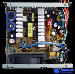
Computer switching power supply (ATX) with the cover removed
A - input rectifier. Below is the input filter
B - input smoothing capacitors. To the right is the high-voltage transistor radiator.
C - pulse transformer. The radiator of low-voltage keys is visible to the right.
D - group stabilization choke (GDS)
E - output filter capacitors
Switching power supplies are an inverter system. In pulsed power supplies, the AC input voltage is first rectified. The resulting DC voltage is converted into rectangular pulses of increased frequency and a specific duty cycle, either supplied to the transformer (in the case of pulsed power supplies with electrical isolation from the supply mains) or directly to the output low-pass filter (in pulse power supplies without electrical isolation). Small-sized transformers can be used in impulse power supplies - this is explained by the fact that with increasing frequency, the efficiency of the transformer increases and the requirements for the core size (cross section) required for transmitting the equivalent power decrease. In most cases, such a core can be made of ferromagnetic materials, in contrast to the cores of low-frequency transformers, for which electrical steel is used.
In pulsed power supplies, voltage regulation is provided by negative feedback. Feedback allows you to maintain the output voltage at a relatively constant level, regardless of fluctuations in the input voltage and the magnitude of the load. Feedback can be organized in different ways. In the case of galvanically isolated switching sources from the mains, the most common methods are using communication through one of the output windings of the transformer or using an optocoupler. Depending on the magnitude of the feedback signal (depending on the output voltage), the duty cycle of the pulses at the output of the PWM controller changes. If isolation is not required, then, as a rule, a simple resistive voltage divider is used. Thus, the power supply maintains a stable output voltage.
Advantages and disadvantages
Advantages of pulse power supplies
Comparable in output power with linear stabilizers, the corresponding pulse stabilizers have the following main advantages:
- less weight due to the fact that with increasing frequency you can use smaller transformers with the same transmitted power. The mass of linear stabilizers is composed mainly of powerful heavy low-frequency power transformers and powerful radiators of power elements operating in linear mode. In addition, due to the increased conversion frequency, the size of the output voltage filter is significantly reduced (capacitors of much lower capacity can be used than for rectifiers operating at an industrial frequency). The rectifier itself can be made according to the simplest half-wave scheme, without the risk of increasing the output voltage ripple;
- significantly higher efficiency (up to 90-98%) [ source not specified 1805 days ] due to the fact that the main losses in the pulse stabilizers are connected by transient processes at the moments of switching the key element. Since most of the time, the key elements are in one of the stable states (that is, either on or off) the energy losses are minimal;
- lower cost due to the massive production of a unified element base and the development of high-power key transistors. In addition, it should be noted that the cost of pulse transformers is much lower with comparable transmitted power, and the possibility of using less powerful power elements, since their mode of operation is key;
- reliability comparable to linear stabilizers.
Power supplies of computer equipment, office equipment, consumer electronics are almost exclusively pulsed. Low-power linear power supplies were preserved mainly only in the following areas:
- to power low-voltage control boards of high-quality household appliances such as washing machines, microwave ovens and heating boilers and speakers;
- for low-power control devices of high and ultra-high reliability, designed for long-term continuous operation in the absence of maintenance or difficult maintenance, such as, for example, digital voltmeters in electric boards, or automation of production processes.
- wide range of supply voltage and frequency, unattainable for a comparable in price linear. In practice, this means the possibility of using the same pulsed power supply unit for portable digital electronics in different countries of the world - Russia / USA / England, which are very different in voltage and frequency in standard outlets.
- the presence of built-in protection circuits in most modern power supply units against various unforeseen situations, for example, from a short circuit and from no load at the output.
Disadvantages of impulse power supplies
- The operation of the main part of the circuit without galvanic isolation from the network, which, in particular, makes it difficult to repair such power supplies;
- Without exception, all pulsed power supplies are a source of high-frequency interference, since this is due to the very principle of their operation. Therefore, it is required to take additional measures of interference suppression, often not allowing to eliminate the interference completely. In this regard, the use of pulsed power supplies for some types of equipment is often unacceptable.
- As a rule, pulse power supplies are limited to the minimum power load. If the load power is below the minimum, the power supply either does not start, or the output voltage parameters (magnitude, stability) may not fit into the tolerance.
- In distributed power systems: the harmonic effect of multiples of three. If there are effective power factor correctors and filters in the input circuits, this disadvantage is usually not relevant.
see also
- Power supply
- Voltage regulator
- Computer power supply
- Charger
Notes

Comments
To leave a comment
Power supplies for electronic equipment
Terms: Power supplies for electronic equipment