Lecture
Take a transformer with two windings: primary - W 1 for connecting to the network and secondary - W 2 for connecting the load. Its simplified device and the conditional-graphic designation in the diagrams is shown in Figure 1.
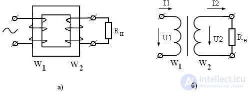
Three transformer operation modes are possible: idling mode (XX), operating mode (nominal) and short circuit mode (SC). Consider the operation of a transformer in these modes.
Idle mode. In this mode, the load resistance is infinite, with the result that the transformer is equivalent to a conventional inductor with a ferromagnetic core. In idle mode, the transformer can be represented by the equivalent circuit, shown in Figure 2.
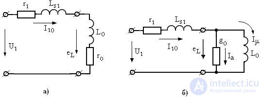
In the equivalent circuit of the transformer shown in Figure 2:
r 1 - the resistance of the primary winding
L S1 - inductance characterizing the dispersion flow of the primary winding
r 0 - the resistance of active losses in the magnetic circuit
L 0 - the main inductance of the primary winding
 (one)
(one)
I μ - the current that creates the main magnetic flux (magnetizing current)
I a - active current loss in the core
I 10 = I a + I μ is the no-load current of the transformer.
The parallel equivalent circuit of a transformer is convenient for constructing a vector diagram of voltages and currents for a real inductor. The vector diagram is shown in Figure 3.
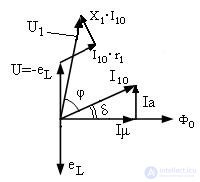
Here δ is the loss angle in the magnetic core
X 1 - resistance to leakage inductance L S1 .
In this case, the EMF vector induced in the winding W 2 (voltage in the secondary winding) coincides in phase with e L , and the voltage U 1 is the sum
 ;
;  (2)
(2)
The losses on the ohmic resistance of the winding are small, since the no-load current is much less than the nominal one and the shear angle between current and voltage ( I 10 and U 1 ) is determined by the losses in the magnetic circuit. From the experience of idling and find the angle of loss δ and calculate the loss in the core.
The transformer is a reversible device (the primary and secondary windings can be swapped!), Therefore for each winding we write the basic formula of the transformer EMF.
 (3)
(3) (four)
Dividing equation (3) by (4), we obtain the expression for the transformation ratio:
 (five)
In idle mode, a transformer determines its transformation ratio.
Operating mode (loaded or nominal). If the secondary winding W 2 connect the load R n , then its voltage U 2 will cause the load current I 2 , as shown in Figure 1b. The currents I 1 and I 2 are oriented differently with respect to the magnetic flux Φ 0 . The current I 1 creates a flow Φ 1 , and the current I 2 creates a flow Φ 2 and seeks to reduce the flow Φ 1 . In other words, magnetic fluxes Φ 1 and Φ 2 appear in the magnetic core, which are directed oppositely according to the Lenz law, and their algebraic sum gives: Φ 1 + Φ 2 = Ф 0 - the magnetic flux of the transformer.
From here you can write the equation of magnetizing forces (the law of total current):
 (6)
(6)
It is seen that a change in current I 2 will necessarily lead to a change in current I 1 . The load forms a second circuit in which the emf of the secondary winding e 2 is a source of energy. At the same time, the following equations are true:
 (7)
(7) (eight)
where r 2 is the ohmic resistance of the secondary winding
x 2 - resistance inductance dissipation of the secondary winding.
According to Kirghoff's law, the sum of currents (6) can be provided by parallel connection of electrical circuits, therefore, in the operating mode, a transformer can be represented by an equivalent circuit shown in Figure 4.
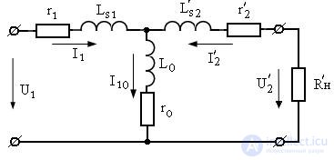
The equivalent circuit of a transformer in the operating mode, shown in Figure 4, is called a T-shaped equivalent circuit or a reduced transformer. Reduction of the secondary winding to the primary is performed under the condition of equality of the full power of the secondary windings  , or
, or  . From this equality, it is possible to obtain formulas for recalculating the voltages and currents of the secondary winding into the primary winding and from them to obtain the reduced values of the load resistances, the secondary winding, and the leakage inductance.
 (9)
(9) (ten)
(ten) (eleven)
 (12)
(12) (13)
(13)
Currents and voltages are given through the transformation ratio, and resistance through the square of the transformation ratio. You can recalculate the secondary circuit in the primary or vice versa.
The representation of a transformer in the form of an equivalent circuit allows the methods of the theory of circuits to calculate any arbitrarily complex circuit with transformers.
Short circuit mode (short circuit) . This mode is in emergency conditions. It is deliberately used only for experimental determination of transformer parameters (inductance dissipation). The measurements are carried out in the following sequence. The input voltage is set to zero. Close the output terminals ( U 2 = 0). Gently raise the input voltage ( U 1 ) until the rated currents are established in the windings. The value U 1 = U short-circuit is called the short-circuit voltage, is the nominal value of the transformer and is usually 5 ... 10% of the nominal voltage U 1nom . At the same time, the no-load current I 10 is very small compared to the nominal one and can be neglected (to be considered equal to zero). Then the equivalent circuit of the transformer in the short-circuit mode takes the form shown in Figure 5.
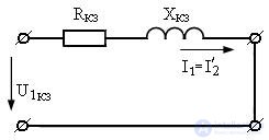
We have taken the no-load current to zero I 10 = 0, therefore in the equivalent circuit of the transformer the parallel circuit L 0 r 0 is absent. The input resistance of the transformer is completely determined by the dispersion inductance of the primary and secondary windings, as well as their ohmic resistance:
 (14)
(14)
The resulting resistance is the short-circuit resistance of the transformer. Knowing the short circuit impedance:

You can find the transfer coefficient of the transformer, and in case of a small inductance of dissipation, the power loss in the transformer windings.

The magnetizing force that creates a magnetic flux in the core in the short circuit mode (measuring mode) is almost zero:


and if I 10 = 0, then I 1 W 1 = - I 2 W 2 from where we find the ratio of currents, and hence the current transformation ratio:
 (15)
(15)
The minus sign in the formula (15) says that the magnetic fluxes Ф 1 and Ф 2 are directed towards each other and are mutually compensated.
If the transformer has several secondary windings , as shown in the conditionally graphic image of the transformer shown in Figure 6a, then the recalculated load resistances on the equivalent circuit are connected in parallel and its equivalent circuit takes the form shown in Figure 6b.
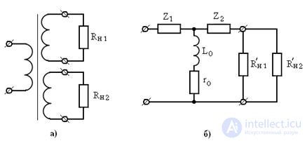
The value of the impedance (impedance) of the secondary windings Z 2 is found as the sum of the resistances of the secondary windings and the resistance of their dissipation inductances:


Comments
To leave a comment
Power supplies for electronic equipment
Terms: Power supplies for electronic equipment