Lecture
In the radio-electronic industry, radio elements operating with a magnetic field are widely used. As an example, you can call inductance, chokes, transformers. Ferromagnets are often used to increase the inductance of these radio elements with the same size and number of turns of the coil. In this case, the properties of a ferromagnet are used to strengthen (concentrate) magnetic fields due to their own magnetization.
When an inductance is operating, it is very important to know the dependence of its inductance on external factors. The main factor influencing the inductance is the magnetic induction of the magnetic core. It, in turn, strongly depends on the magnetic field acting on the magnetic core. We investigate this dependence. The cores are of various shapes, but the most effective are the cores of the closed shape (the magnetic field lines are always closed). To create a magnetic field in a ferromagnetic core, we wind a wire on it and pass current through it, as shown in Figure 1.
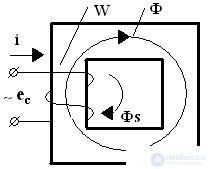
A variable external EMF e with frequency f c is supplied to the coil, W is the number of turns in the winding. When current i flows in the core, a magnetic flux F is generated , which mainly closes along the core, since the magnetic resistance of air is μ times larger than that of the core (μ is the relative magnetic permeability). Part of the magnetic flux closes, bypassing the core - this is the scattering flux Фs . While the scattering flow is neglected.
If the core was initially fully demagnetized, then the process of its magnetization in the coordinates induction-intensity goes along the line 0 - b (Figure 2). In this figure: В - magnetic induction Вб / м 2 = Tesla, Н - magnetic field strength (А / m).
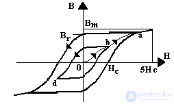
When the external emf changes sign, the core is reversal in the other direction, but it will never return to point 0. The operating point moves along a partial hysteresis loop (bdb). If you increase the external emf, the loop area increases. The top of the loop goes from point b to point a. In the end, a moment comes when an increase in the EMF does not lead to an increase in the area of the hysteresis loop, which in this case is called the limit cycle curve. It cuts off the segment H C on the abscissa axis, called the coercive force, and on the ordinate axis the segment B r - residual induction. Induction in a core with a tension H = 5H C is called maximum induction - Bm. The values of Br, H C, and Bm are reference parameters of the magnetic material. Recall also that μ а = В / Н - absolute magnetic permeability, μ 0 = 4 π 10 −7 [GN / m] - vacuum magnetic permeability, μ = μ a / μ0 - relative magnetic permeability (dimensionless quantity), inductance is measured in Henry - [H] = [V × s / a] = [Ohm * s], the magnetic flux F is measured in Weber - [Wb] = [V * s], the ratio Br / Bm = P is the squareness coefficient of the magnetic material.
The locus of the points of the tops of the partial hysteresis loops is the main magnetization curve B (H), which is shown in Figure 3.
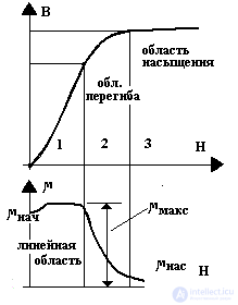
Figure 4 shows the dependence μ (H). Three areas are distinguished here: 1 — linear (almost!), 2 — the inflection region, and 3 — the saturation region. In the first area, power transformers and chokes of smoothing filters work, in the second - magnetic amplifiers, in the third - magnetic switches (saturation chokes). For calculations, the magnetization curve is linearized, counting on the linear section μ beg = μ max = μ a .
The parameters of the core are determined by the properties of the magnetic material and very significantly by the design of the magnetic circuit. Various high carbon steels, permalloys, magnetodielectrics and ferrites are used as magnetic materials. Depending on the manufacturing technology distinguish the core plates, tape and extruded. At frequencies of 50 ... 400 Hz, steel is used in the form of tapes or plates with a thickness of 0.3 ... 0.5 mm, and at frequencies of 400 ... 1000 Hz - 0.1 ... 0.2 mm. At higher frequencies, permalloy, magnetodielectrics and ferrites are used.
Permalloy - iron-nickel alloy - steel with a high percentage of Cr, Ni, Mn, Co, Mo. Used in the form of ribbons with a thickness of 5 ... 20 microns. This is a "soft magnetic" material (narrow hysteresis loop - Нс less than 5 A / m).
Magnetodielectric is a finely dispersed ferromagnetic powder, formed into cores by a binder based on polystyrene. Used at high frequencies (1 ... 500 kHz). These are alsifera and pressed permalloy - presperm (permalloy powder!).
Ferrite is a ferromagnetic powder, sintered at high temperature (~ 1200 ° С) and pressure up to 30 atm. Ferrites are more technological and cheaper in production, but in the temperature range from −60 to + 125 ° С their induction varies by ± 30%, and in permalloy by ± 5%. Table 1 shows the characteristics of some magnetic materials.

Comments
To leave a comment
Power supplies for electronic equipment
Terms: Power supplies for electronic equipment