Lecture
Losses in the magnetic core substantially depend on the frequency of the magnetic field acting on it. Therefore, the losses in the magnetic core are divided into:
Static losses are the losses due to magnetization reversal of the magnetic circuit. The magnetic flux, passing through the core, turns all the domains either in the direction of the magnetic field or in the opposite direction, while the field does the work: the crystal lattice moves apart, heat is generated and the magnetic core is heated. Static losses are proportional to the area of the loop (S loop ), frequency ( f network ) and weight ( G ) of the core:
P g ≡ S loop × f network × G.This is the so-called hysteresis loss. The narrower the loop, the smaller the loss. As the tape thickness decreases, Hc increases, the loop area increases, and hysteresis losses increase. As the field frequency increases, μ a decreases and losses also increase.
Dynamic losses are the eddy current losses. The hysteresis loop, taken at a constant current ( f c = 0) is called a static loop. With increasing frequency f c, eddy currents begin to have an effect on this graph.
Ferromagnet (steel) is a good electrical conductor, so the magnetic flux, passing through the core, induces currents in it that cover each magnetic field line. These currents create their own magnetic fluxes directed towards the main magnetic flux. The result of the addition of induced currents in the thickness of the magnetic circuit is such that the total current is displaced to the edges of the massive magnetic circuit, as shown in Figure 1.

Between the power lines, the currents are compensated and, as a result, the current flows only along the perimeter. Steel has a low ohmic resistance, so the current reaches values of hundreds and thousands of amperes, causing the magnetic core to heat up. To reduce eddy currents, it is necessary to increase the ohmic resistance, which is achieved by a set of core of insulated plates. The thinner the plate (tape), the higher its resistance and less eddy currents. Depending on the operating frequency, the thickness (Δ) of the plates (tape) is different. Table 1 shows the dependence of the thickness of the plates on the network frequency
Table 1. Plate thickness depending on the network frequency| Network frequency f c (Hz) | Plate thickness Δ (mm) |
|---|---|
| 50 ... 60 | 0.5 ... 0.35 |
| 400 | 0.2 ... 0.1 |
| 20,000 | 0.05 ... 0.003 |
The eddy current losses are proportional to the square of the frequency, the square of the thickness and the weight of the core P in ≡ f 2 × Δ 2 × G. Therefore, at high frequencies very thin materials are used. Ferrites have the least losses - ferromagnetic powder is sintered at high temperature. Each grain is insulated with oxide, therefore the eddy currents are very small. The last row of table 1 corresponds to this very variant of manufacturing a magnetic core.
Total losses in the magnetic core (P MAG ) are equal to the sum of static and dynamic losses:
P MAG = P g + P c .In reference books on magnetic materials, the loss of P g and P in is not divided, but the total loss per 1 kg of material is given - P beats [W / kg]. The total losses are found by simple multiplication of the specific losses by the core weight.
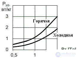
P MAG = P beats × G (2)Since the losses are a multiparameter value, then reference books provide tables or graphical dependences of specific losses on one or another parameter. For example, figure 2 shows the dependences of losses on induction for steel with a thickness Δ = 0.35 mm at a frequency f = 50 Hz for different types of rolled products.
For other frequencies such dependencies will be different. If the mode of operation of the magnetic circuit does not correspond to the mode of measuring losses, then the losses can be recalculated to the required mode using an empirical, but quite suitable formula:
 (3)
(3) where α , β = 1,3 ... 2 are empirical coefficients, which with sufficient accuracy for practice can be taken equal to 2;
f 0 A b0
  - measurement mode for which graphs are provided (or tabular reference data);
     f x , B x - mode of operation for which you want to find the loss.
Table 2 shows the approximate specific losses of some ferromagnetic materials used in the magnetic circuits of transformers and inductors.
Table 2. Specific losses of some ferromagnetic materials| Mark | Frequency, kHz | P beats W / kg | Thickness, mkm |
|---|---|---|---|
| 3414 | 0.4 ... 20 | 22 ± 2 | 80 |
| 50NP | 0.4 ... 20 | 14 ± 2 | 50 |
| 50NP | one | five | 20 |
| 80НХС | one | 1.5 | ten |
| 79НМ | one | 1.5 | ten |
| M2000 NM-A | 0.4 ... 100 | 32 ± 7 | |
| M2000 NM-A | 100 ... 1000 | 13 ± 3 | |
| M2000 HM1-17 | 0.4 ... 100 | 63 ± 10 | |
| M2000 HM1-17 | 100 ... 1000 | 25 ± 4 | |
| M3000 IA | 0.4 ... 200 | 48 ± 8 | |
| M10000 HM1 | 0.4 ... 100 | 5.2 ± 1 |
It can be seen that the loss in permalloy depends on the thickness of the tape. Loss in ferrites at a high frequency is less than at a low frequency due to a reduction in hysteresis losses. Usually the question of the choice of material for the core is solved from the position of the smallest power loss.

Comments
To leave a comment
Power supplies for electronic equipment
Terms: Power supplies for electronic equipment