Lecture
Let's start with the basics. The power supply in the computer performs three functions. First, the alternating current from the household power network needs to be converted to direct current. The second task of the PSU is to reduce the voltage of 110-230 V, redundant for computer electronics, to the standard values required by the power converters of individual PC components - 12 V, 5 V and 3.3 V (as well as negative voltages, which will be discussed later) . Finally, the PSU plays the role of a voltage stabilizer.
There are two main types of power sources that perform the listed functions - linear and pulsed. The simplest linear power supply unit is based on a transformer on which the AC voltage is reduced to the required value, and then the current is rectified by a diode bridge.
However, the PSU is also required to stabilize the output voltage, which is caused by both the instability of the voltage in the household network and the voltage drop in response to an increase in the current in the load.
To compensate for the voltage drop, in a linear power supply unit, transformer parameters are calculated so as to provide excess power. Then at high current in the load the required voltage will be observed. However, an increased voltage, which will occur without any means of compensation at low current in the payload, is also unacceptable. Excessive voltage is eliminated due to the inclusion of non-useful load in the circuit. In the simplest case, such is a resistor or transistor connected via a zener diode (Zener diode). In the more advanced, the transistor is controlled by a microcircuit with a comparator. However, excess power is simply dissipated as heat, which negatively affects the efficiency of the device.
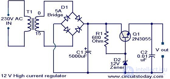
An example of a linear power supply with a stabilizer. Excess power is dissipated in transistor Q1
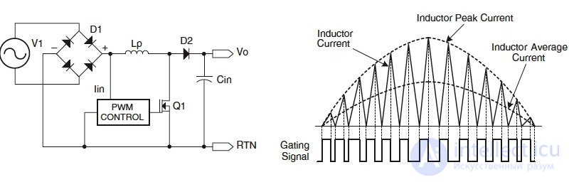
In the pulsed power supply circuit, another variable arises, on which the output voltage depends, in addition to the two already existing: the input voltage and the load resistance. Consistent with the load is the key (which in the case of interest is the transistor), controlled by the microcontroller in the pulse-width modulation (PWM) mode. The higher the duration of the open states of the transistor with respect to their period (this parameter is called the duty cycle, in Russian terminology the return value is used - the duty cycle), the higher the output voltage. Due to the presence of the key, the switching unit is also called Switched-Mode Power Supply (SMPS).
No current flows through the closed transistor, and the resistance of the open transistor is ideally negligible. In fact, an open transistor has resistance and dissipates some of the power as heat. In addition, the transition between the states of the transistor is not perfectly discrete. Nevertheless, the efficiency of a pulsed current source can exceed 90%, while the efficiency of a linear power supply unit with a stabilizer at best reaches 50%.
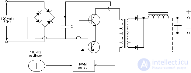
Simplest AC / DC Pulse Converter with Transformer
Another advantage of switching power supplies is a radical reduction in the size and weight of the transformer compared to linear power supplies of the same power. It is known that the higher the frequency of the alternating current in the primary winding of the transformer, the smaller the required size of the core and the number of turns of the winding. Therefore, the key transistor in the circuit is not placed after, but before the transformer and, in addition to voltage stabilization, is used to produce high frequency alternating current (for computer power supplies this is from 30 to 100 kHz and higher, and usually around 60 kHz). A transformer operating at a frequency of 50–60 Hz for the power required by a standard computer would be tens of times more massive.
Linear power supplies today are used mainly in the case of low-power devices, when the relatively complex electronics required for a switching power supply is a more sensitive item of expenditure compared to a transformer. These are, for example, 9 V power supplies, which are used for guitar effects pedals, and once for gaming consoles, etc. But the chargers for smartphones are already completely impulse - here the costs are justified. Due to the significantly lower amplitude of voltage ripple at the output, linear power supply units are also used in those areas where this quality is in demand.
The desktop computer power supply unit is a switching power supply, the input of which is supplied with a voltage of a household electrical network with parameters 110/230 V, 50-60 Hz, and the output has a number of DC lines, the main ones of which are 12, 5 and 3.3 V nominal In addition, the power supply unit provides a voltage of -12 V, and once also a voltage of -5 V, necessary for the ISA bus. But the latter at some point was excluded from the ATX standard due to the termination of support for ISA itself.
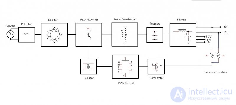
The block diagram of the pulse BP
In the simplified scheme of a standard impulse power supply unit presented above, four main stages can be distinguished. In the same order, we consider the components of power supplies in reviews, namely:
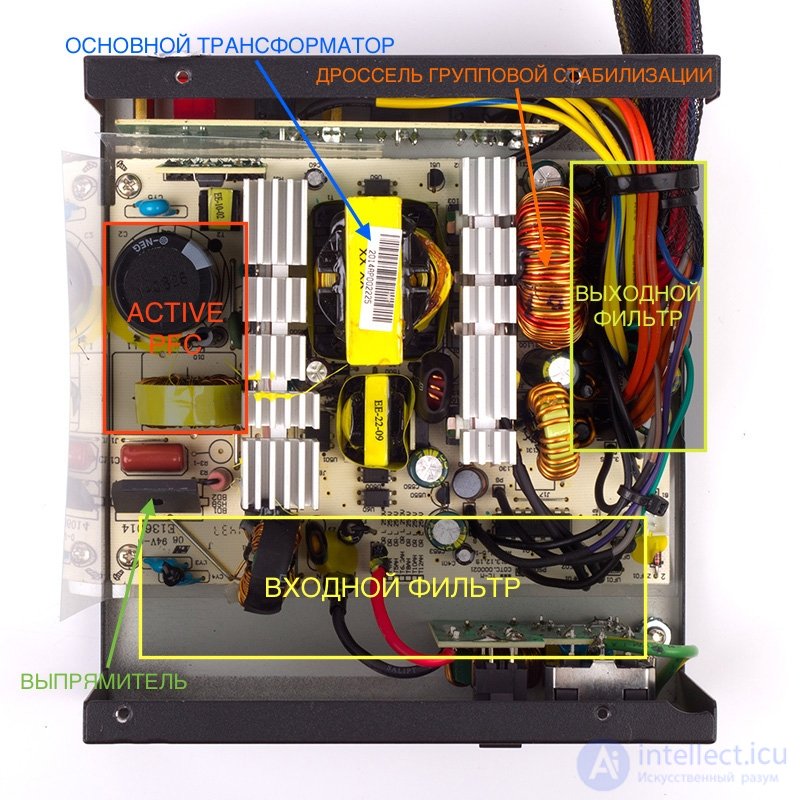
The internal structure of the PSU (AeroCool KCAS-650M)
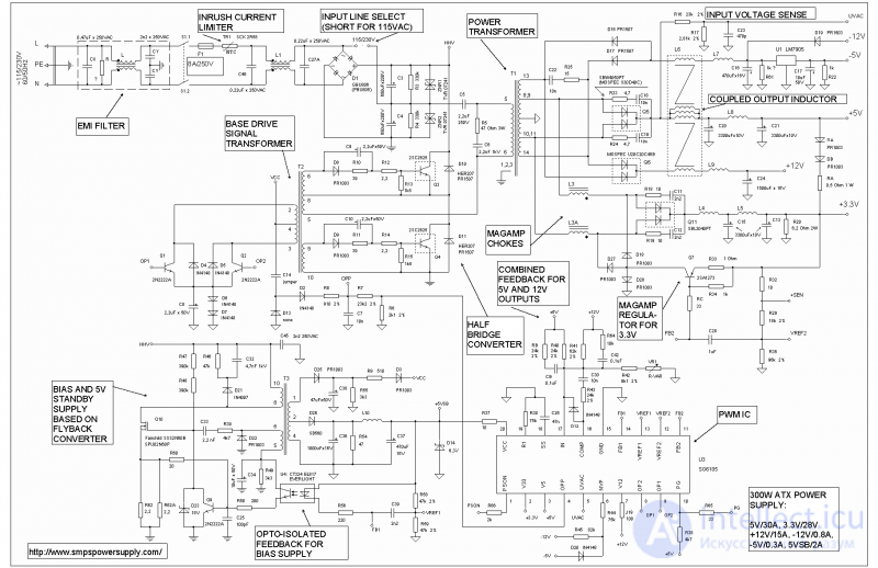
The complete layout of a simple ATX power supply
The filter at the input of the power supply unit is used to suppress two types of electromagnetic interference: differential (differential-mode) - when the noise current flows in different directions in the power lines, and common mode (common-mode) - when the current flows in one direction.
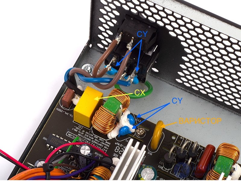
Differential interference is suppressed by a CX capacitor (a large yellow film capacitor in the photo above) connected in parallel with the load. Sometimes an additional choke is added to each wire, which performs the same function (not in the diagram).
The common mode filter is formed by CY capacitors (blue drop-shaped ceramic capacitors in the photo), at a common point connecting the power lines to the ground, and so on. common mode choke (LF1 in the circuit), the current in two windings of which flows in one direction, which creates resistance for common mode interference.
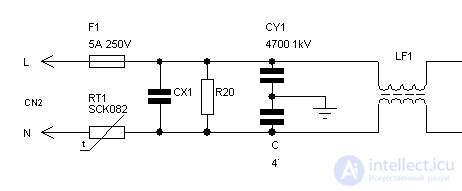
EMI filter circuit
In low-cost models, a minimum set of filter parts is installed, in more expensive, the described schemes form repeating (fully or partially) links. In the past, BPs were often encountered without an EMF filter at all. Now it is rather a curious exception, although by buying a very cheap power supply, you can still run into such a surprise. As a result, the computer itself will suffer not only and not so much as the other equipment included in the household network - impulse power supplies are a powerful source of interference.
In the area of the filter good BP you can find several parts that protect the device itself or its owner from damage. Almost always there is the simplest fuse to protect against short circuits (F1 in the diagram). Note that when the fuse trips, the protected object is no longer the power supply. If a fault occurs, it means that the key transistors have already pierced, and it is important to at least prevent the wiring from burning. If the power supply fuse in the power supply suddenly burnt out, then changing it to a new one, most likely, is already meaningless.
Protection against short-term power surges using a varistor (MOV - Metal Oxide Varistor) is performed separately. But there are no means of protection against long-term overvoltage in computer power supplies. This function is performed by external stabilizers with their own transformer inside.
EMI filter (Antec VP700P)
A capacitor in the PFC circuit after the rectifier can retain a significant charge after disconnecting from the power supply. In order for a careless person, who pokes a finger in the power connector, does not hit with a current, a large-value discharging resistor is installed between the wires. In a more sophisticated version - along with the control circuit, which does not allow the charge to flow away when the device is working.
By the way, the presence of a filter in the power supply unit of the PC (and it also exists in the power supply unit of the monitor and practically any computer equipment) means that buying a separate “network filter” instead of the usual extension cord is, in general, to no avail. It's all the same inside. The only condition in any case is normal three-pole wiring with grounding. Otherwise, capacitors CY connected to ground simply cannot perform their function.
After the filter, the alternating current is converted into direct current by means of a diode bridge, usually in the form of an assembly in a common housing. A separate radiator for cooling the bridge is highly recommended. The bridge, assembled from four discrete diodes, is an attribute of cheap power supplies. You can also ask about what current the bridge is designed to determine if it corresponds to the power of the power supply itself. Although this parameter, as a rule, there is a good stock.
In an alternating current circuit with a linear load (such as an incandescent lamp or electric stove), the flowing current follows the same sine wave as the voltage. But this is not the case with devices that have an input rectifier, such as pulsed power supplies. The power supply unit transmits a current with short pulses approximately coinciding in time with the peaks of the sinusoid voltage (that is, the maximum instantaneous voltage) when the rectifier smoothing capacitor is charged.
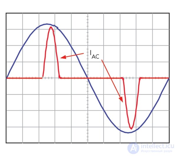
Current consumption pulsed power supply
The current signal of the distorted form is decomposed into several harmonic oscillations in sum with a sinusoid of a given amplitude (an ideal signal that would have occurred under a linear load).
The power used to perform useful work (which, in fact, is the heating of PC components), is indicated in the characteristics of the PSU and is called active. The rest of the power generated by the harmonic oscillations of the current is called reactive. It does not produce useful work, but heats the wires and creates a load on transformers and other power equipment.
The vector sum of reactive and active power is called apparent power. And the ratio of active power to full is called a power factor (power factor) - not to be confused with efficiency!
In the case of a pulsed power supply, the power factor is initially quite low - about 0.7. For a private consumer, reactive power is not a problem (since it is not taken into account by electricity meters), unless he uses a UPS. On the bespereboynik just the full power of the load falls. On the scale of an office or a city network, excess reactive power generated by pulsed power supplies already significantly reduces the quality of power supply and causes costs, therefore, it is actively struggling with it.
Wiring diagram and current consumption by Active PFC unit
In particular, the vast majority of computer power supply units are equipped with active power factor correction circuits (Active PFC). A unit with an active PFC is easily recognized by a single large capacitor and a choke installed after the rectifier. In essence, Active PFC is another pulse converter that maintains a constant charge of about 400 V. A capacitor is consumed by short pulses, the width of which is chosen so that the signal is approximated by a sinusoid - which is required to simulate a linear load. . To synchronize the current consumption signal with the voltage sine wave, the PFC controller has a special logic.
The active PFC circuit contains one or two key transistors and a powerful diode, which are placed on the same radiator with the key transistors of the main converter BP. As a rule, the PWM controller of the key of the main converter and the Active PFC key are one chip (PWM / PFC Combo).

Active PFC unit and input rectifier (Antec VP700P)
The power factor of pulsed power supplies with active PFC reaches 0.95 and higher. In addition, they have one additional advantage - the 110/230 V mains switch and the corresponding voltage doubler inside the power supply unit are not required. Most PFC circuits digest voltages from 85 to 265 V. In addition, the sensitivity of the PSU to short-term voltage dips decreases.
By the way, in addition to the active correction of PFC, there is also a passive one, which implies installing a large inductance choke in series with the load. Its effectiveness is small, and in modern BP you can hardly find such a thing.
The general principle of operation for all pulsed power supplies of an isolated topology (with a transformer) is one: the key transistor (or transistors) creates alternating current on the transformer primary winding, and the PWM controller controls the duty cycle of their switching. Specific schemes, however, differ both in the number of key transistors and other elements, and in quality characteristics: efficiency, signal form, interference, etc. But here too much depends on the specific implementation, so that it is worth paying attention to. For those interested, we present a set of diagrams and a table that will allow us to identify them in specific devices by the composition of the parts.
| Transistors | Diodes | Capacitors | Transformer primary winding legs | |
| Single-Transistor Forward | one | one | one | four |
| Two-Transistor Forward | 2 | 2 | 0 | 2 |
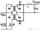
| Half bridge | 2 | 0 | 2 | 2 |
| Full Bridge | four | 0 | 0 | 2 |
| Push pull | 2 | 0 | 0 | 3 |
In addition to the listed topologies, there are resonant Half Bridge variants in expensive power supplies, which are easily identified by an additional large choke (or two) and a capacitor forming an oscillating circuit.
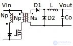
Single-Transistor Forward |

Two-Transistor Forward |
Push pull |
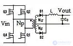
Full Bridge |
Half bridge |
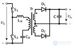
Resonant Half-Bridge |
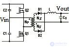
The secondary circuit is all that is after the secondary winding of the transformer. In most modern power supplies, the transformer has two windings: 12 V is removed from one of them, and 5 V on the other. The current is first straightened using an assembly of two Schottky diodes — one or more to the bus (12 V on the busiest bus in powerful BP there are four assemblies). More efficient in terms of efficiency are synchronous rectifiers, in which field-effect transistors are used instead of diodes. But this is the prerogative of the truly advanced and expensive power supply units that claim to be 80 PLUS Platinum certified.
The 3.3 V bus is usually output from the same winding as the 5 V bus, only the voltage is reduced using a saturated choke (Mag Amp). A special winding on a transformer for 3.3 V is an exotic option. Of the negative voltages in the current ATX standard, only -12 V is left, which is removed from the secondary winding under a 12 V bus through separate low-voltage diodes.
The PWM control of the converter key changes the voltage on the primary winding of the transformer, and therefore on all the secondary windings at once. At the same time, the current consumption of a computer is not evenly distributed between the power supply busbars. In modern gland, the busiest one is 12-B.
For separate stabilization of voltages on different tires, additional measures are required. The classic method involves the use of the throttle group stabilization. Three main tires are passed through its windings, and as a result, if a current increases on one bus, the voltage drops on the others. For example, on a 12 V bus, the current increased, and to prevent a voltage drop, the PWM controller reduced the duty cycle of the transistors of the key transistors. As a result, the voltage on the 5 V bus could go beyond the permissible limits, but the group stabilization was suppressed by a choke.
The voltage on the 3.3 V bus is additionally regulated by another saturable choke.
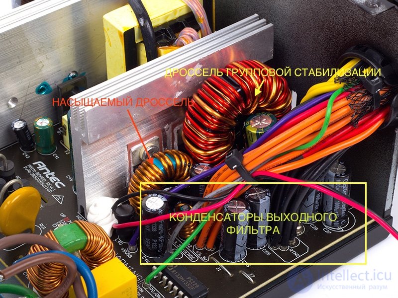
Стабилизирующие дроссели и выходной фильтр (Antec VP700P)
В более совершенном варианте обеспечивается раздельная стабилизация шин 5 и 12 В за счет насыщаемых дросселей, но сейчас эта конструкция в дорогих качественных БП уступила место преобразователям DC-DC. В последнем случае трансформатор имеет единственную вторичную обмотку с напряжением 12 В, а напряжения 5 В и 3,3 В получаются благодаря преобразователям постоянного тока. Такой способ наиболее благоприятен для стабильности напряжений.
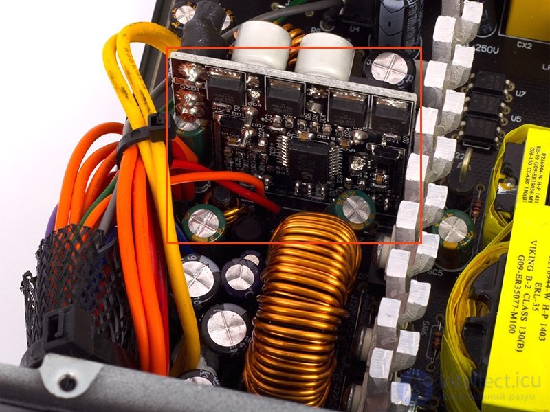
Преобразователь DC-DC для шины 5 В (CoolerMaster G650M)
Выходной фильтр
Финальной стадией на каждой шине является фильтр, который сглаживает пульсации напряжения, вызываемые ключевыми транзисторами. Кроме того, во вторичную цепь БП в той или иной мере пробиваются пульсации входного выпрямителя, чья частота равна удвоенной частоте питающей электросети.
В состав фильтра пульсаций входит дроссель и конденсаторы большой емкости. Для качественных блоков питания характерна емкость не менее 2 000 мкФ, но у производителей дешевых моделей есть резерв для экономии, когда устанавливают конденсаторы, к примеру, вдвое меньшего номинала, что неизбежно отражается на амплитуде пульсаций.
Описание компонентов блока питания было бы неполным без упоминания об источнике дежурного напряжения 5 В, который делает возможным спящий режим ПК и обеспечивает работу всех устройств, которые должны быть включены постоянно. «Дежурка» питается от отдельного импульсного преобразователя с маломощным трансформатором. В некоторых БП встречается и третий трансформатор, использующийся в цепи обратной связи для изоляции ШИМ-контроллера от первичной цепи основного преобразователя. В других случаях эту функцию выполняют оптопары (светодиод и фототранзистор в одном корпусе).
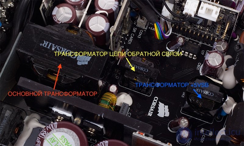
Трансформаторы (Corsair HX750i)
Одним из основных параметров БП является стабильность напряжений, которая находит отражение в т.н. кросс-нагрузочной характеристике. КНХ представляет собой диаграмму, в которой на одной оси отложен ток или мощность на шине 12 В, а на другой – совокупный ток или мощность на шинах 3,3 и 5 В. В точках пересечения при разных значениях обеих переменных определяется отклонение напряжения от номинала на той или иной шине. Соответственно, мы публикуем две разные КНХ – для шины 12 В и для шины 5/3,3 В.
Цвет точки означает процент отклонения:
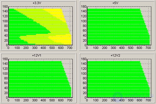
Пример отличной КНХ (Corsair HX750i)
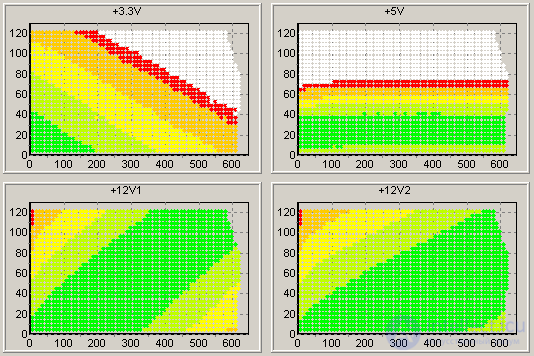
Посредственная КНХ (Antec VP700P)
Для получения КНХ используется сделанный на заказ стенд для тестирования блоков питания, который создает нагрузку за счет рассеивания тепла на мощных полевых транзисторах.

Стенд для тестирования БП
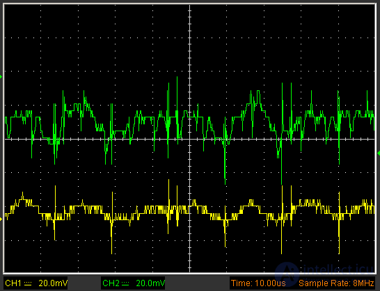
Другой не менее важный тест – определение размаха пульсаций на выходе БП. Стандарт ATX допускает пульсации в пределах 120 мВ для шины 12 В и 50 мВ – для шины 5 В. Различают высокочастотные пульсации (на удвоенной частоте ключа основного преобразователя) и низкочастотные (на удвоенной частоте питающей сети).
Этот параметр мы измеряем при помощи USB-осциллографа Hantek DSO-6022BE при максимальной нагрузке на БП, заданной спецификациями. На осциллограмме ниже зеленый график соответствует шине 12 В, желтый – 5 В. Видно, что пульсации находятся в пределах нормы, и даже с запасом.
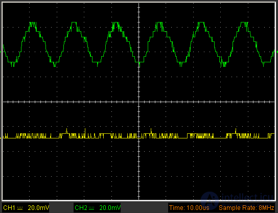
Высокочастотные пульсации: хороший результат (AeroCool KCAS-650M)
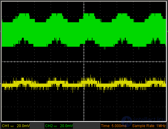
Низкочастотные пульсации: хороший результат (AeroCool KCAS-650M)
Для сравнения приводим картину пульсаций на выходе БП старого компьютера. Этот блок изначально не был выдающимся, но явно не стал лучше от времени. Судя по размаху низкочастотных пульсаций (обратите внимание, что деление развертки напряжения увеличено до 50 мВ, чтобы колебания поместились на экран), сглаживающий конденсатор на входе уже пришел в негодность. Высокочастотные пульсации на шине 5 В находятся на грани допустимых 50 мВ.
Высокочастотные пульсации: на грани допустимого (старый БП)
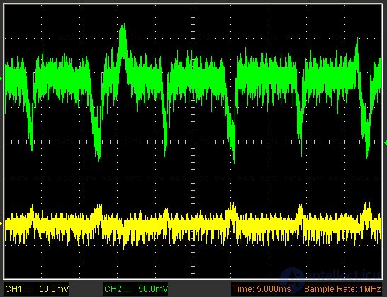
Низкочастотные пульсации: ужасно (старый БП)
В следующем тесте определяется КПД блока при нагрузке от 10 до 100% от номинальной мощности (путем сравнения мощности на выходе с мощностью на входе, измеренной при помощи бытового ваттметра). Для сравнения на графике приводятся критерии различных категорий 80 PLUS. Впрочем, большого интереса в наши дни это не вызывает. На графике приведены результаты топового БП Corsair в сравнении с весьма дешевым Antec, а разница не то чтобы очень велика.
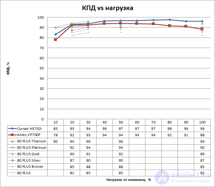
График КПД
Более насущный для пользователя вопрос – шум от встроенного вентилятора. Непосредственно измерить его вблизи от ревущего стенда для тестирования БП невозможно, поэтому мы измеряем скорость вращения крыльчатки лазерным тахометром – также при мощности от 10 до 100%. На нижеприведенном графике видно, что при низкой нагрузке на этот БП 135-миллиметровый вентилятор сохраняет низкие обороты и вряд ли слышен вообще. При максимальной нагрузке шум уже можно различить, но уровень все еще вполне приемлемый.
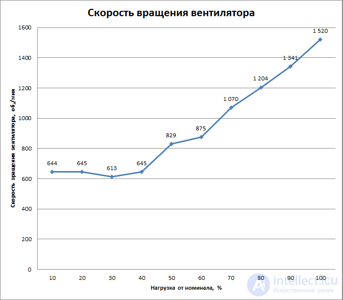
График скорости вращения вентилятора (AeroCool KCAS-650M)

Comments
To leave a comment
Power supplies for electronic equipment
Terms: Power supplies for electronic equipment