Lecture
The infological aspect is meant when considering issues related to the semantic content of data, with their semantics, regardless of the way the computer system is presented in memory. At the stage of the infological information system design, the following issues are resolved:
Thus, at this stage, the selection and description of a part of the real world is made, which must be represented in the information system, that is, the subject area (software) of the designed database is determined.
Database design is the process of creating a database schema and determining the necessary integrity constraints.
Main tasks:
Conceptual (infological) design is the construction of a semantic domain model, that is, an information model of the highest level of abstraction. Such a model is created without targeting any specific DBMS and data model. The terms "semantic model", "conceptual model" and "infological model" are synonymous. In addition, in this context, the words “database model” and “domain model” (for example, “conceptual database model” and “conceptual domain model”) can be used equally, because such a model is both an image of reality and projected database for this reality.
The specific type and content of the conceptual model of the database is determined by the formal apparatus chosen for this. Graphic notations similar to ER diagrams are commonly used.
Most often, the conceptual database model includes:
Logical (datalogical) design - creating a database schema based on a specific data model, for example, the relational data model. For a relational data model, the datalogical model is a set of relationship schemes, usually with primary keys, as well as “connections” between relations, which are foreign keys.
The transformation of a conceptual model into a logical model, as a rule, is carried out according to formal rules. This stage can be largely automated.
At the stage of logical design, the specifics of a particular data model are taken into account, but the specifics of a specific DBMS may not be taken into account.
Physical design - creating a database schema for a specific DBMS. The specifics of a particular DBMS may include restrictions on the naming of database objects, restrictions on the supported data types, etc. In addition, the specifics of a specific DBMS in physical design includes the choice of solutions related to the physical storage medium (selection of disk memory management methods, separation of databases by files and devices, data access methods), creation of indexes, etc.
When designing relational databases, so-called normalization is usually performed.
The “entity-relationship” model (the “Entity-Relationship model” ), or the ER-model proposed by P. Chen [1] in 1976, is the most well-known representative of the class of semantic (conceptual, infological) domain models. The ER model is usually presented in graphical form, using P. Chen’s original notation, called the ER diagram , or using other graphic notations ( Crow's Foot , Information Engineering , etc.).
The main advantages of ER-models:
The main elements of ER-models:
Entity - an object of the subject area, with attributes.
The relationship between entities is characterized by:
The semantic model (conceptual model, infological model) is a domain model, designed to represent the semantics of the domain at the highest level of abstraction. This means that the need to use the concepts of "low level" associated with the specifics of the physical representation and storage of data is eliminated or minimized.
Date K. Dzh. Introduction to database systems. - 8th ed. - M .: "Williams", 2006:
Semantic modeling has been the subject of intense research since the late 1970s. The main motive for such studies (ie, the problem that the researchers tried to solve) was the following fact. The fact is that database systems usually have very limited information about the meaning of the data stored in them. Most often they allow only to manipulate data of certain simple types and define some of the simplest integrity constraints imposed on this data. Any more complex interpretation is left to the user. However, it would be great if the systems could have a slightly wider amount of information and be more intelligent to respond to user requests, as well as support more complex (that is, higher-level) user interfaces.
[...]
Ideas of semantic modeling can be useful as a tool for designing a database even in the absence of their direct support in a DBMS.
The most well-known representative of the class of semantic models is the “entity-relationship” model (ER-model).
Question: What is an object ?
Answer: Everything!
C. J. Date
The initial stage of database design, the so-called stage of infological design, is to determine what information about the subject area should be presented in the database. A specific information system with a database is developed to meet the information needs of a specific circle of users. Under the subject area understand the part of the real world, information about which is of interest to these users.
Thus, at this stage, the question arises of building a certain semantic domain model, reflecting the necessary information about the selected subject domain. As such a model, widely used at the stage of infological database design, is the so-called Entity / Relationship Model, abbreviated as “ ER-model ”, proposed in 1976 by Chen (Peter Pin-Shan Chen).
What questions need to be answered at this stage?
As a result of the analysis of the subject area by abstraction, entities ( objects ) should be selected, information about which should be presented in the database, as well as the properties of these entities and the connections between them. For example, for a subject area related to university information, such objects might be: students, teachers, faculties, departments, disciplines, etc.
Abstracting allows you to determine the essential in terms of the problem being solved, the characteristics of objects in the domain that allow you to select these objects from a variety of other objects.
Any selected object - the essence of the subject area is characterized by its properties . In fact, the initial selection in the model of the set of objects-entities of the domain consists in the definition and selection of the set of essential properties of these objects.
In determining the properties of entities, it is important to distinguish between two fundamentally different types of these properties.
First, these are properties that allow you to identify specific objects, thanks to which, in fact, it turns out to be possible to select a specific object-entity from a variety of other objects of the domain. Moreover, the very concept of an entity can be defined as something that can be uniquely identifiable in the subject area.
Other properties of objects, in contrast, allow us to establish commonality between different entities. The values of such properties allow the classification of objects , that is, to combine objects that have common properties into certain types or classes of objects. These types ( classes ) themselves are in essence also entities of the domain, but more abstract , generalizing properties of some set of instances of similar objects. The relationship between an entity-class and an entity that is an instance of this class is called an abstract-specific or common-private relation.
Thus, at the initial stage of building an infological model of the domain, the following tasks are solved:
For example, in a certain subject area, separate “persons” —Ivanov, Petrov, Sidorov, etc. — can be distinguished as instance objects. For each of these objects, properties are identified that allow them to be identified, for example passport data, pension insurance number or other signs. Also, in the context of the problem being solved, properties are determined that allow these objects to be combined into abstract types of entity objects, for example, a set of “persons” united by a student , employee , manager , etc.
In other words, at this design stage, an infological model represents a subject area in the form of a set of instances of various entity objects, their abstract types (classes), describing subsets of single-type instances, and sets (aggregation) of properties, which allow to assign specific instances of objects to a particular type. .
Graphically, such a representation of the domain can be represented using a diagram similar to that shown in Fig. one.
.
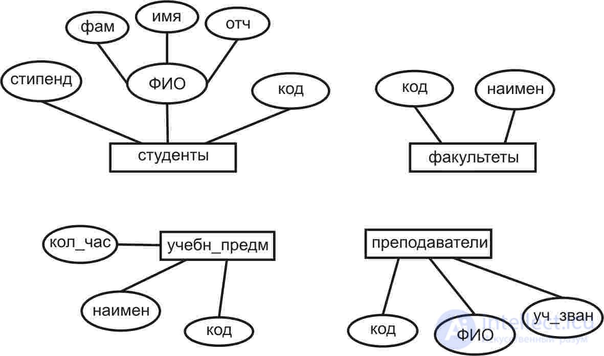
Fig. 1. An example of a diagram of entities of the domain and their properties
As can be seen from the figure, four entities ( such as entities) are distinguished in the above subject area: Students, Teachers, Faculties, and Disciplines (indicated in the diagram by rectangles). Instances belonging to each of these types of entities are characterized by certain sets of properties (indicated by ovals). The set of properties allows you to distinguish between the types of selected entities. Instances of specific entities differ in their property values . In the general case, each specific instance can be identified by a set of all values of its properties (otherwise, we would simply have no way to distinguish two instances from each other). However, entities can usually be identified not by the full set of values of its properties, but by part or even by a single property. This set of properties that allows you to uniquely identify instances of an entity is called an entity identifier or its key .
In practice, an artificial property-identifier is often specially introduced for an entity, the purpose of which is precisely and only to identify its instances. In the diagram above, an example of such a specially introduced identifier property is the Code property of entities Students, Teachers, Faculties and Discipline, which, for example, accepts numeric values of integer type (unsigned integers). At the same time, for a particular type of entity, for example, Students, the presence of two copies (two specific students) with the same values of the Code property is not allowed.
Regarding the properties of entities, it can also be noted that, in general, their value does not have to be a simple (scalar) element. For example, in fig. 1 shows the property of the full name of the Student entity, which is a composite, representing the aggregation of the three simple properties Fam (last name), First Name and Father (middle name).
The next step in the analysis of the subject area in the construction of an infological model is the definition of relationships ( connections ) in which the objects that make up this subject area are located.
The real objects of the domain are not isolated from each other, but are in various connections with each other. For example, entities Students and faculties are related to the fact that specific students study at certain faculties, entities Suppliers and Products are related to the fact that specific suppliers supply certain goods, etc. Information about the relationships between entities is also an important part of all information about the subject area and must also be somehow represented in the database. Obviously, in the formation of a domain model, it is necessary to single out the essential connections-relationships, the materiality of which is determined by the context of the problem being solved, from the whole variety of real connections. Relationships between the same objects that are relevant to one task may not have any meaning in the context of another task.
As well as for the objects themselves, for relations between objects it is advisable to distinguish between instances of relationships, that is, relationships that take place between specific instances of objects, and types ( classes ) of relationships, which are abstractions that generalize the relationships between sets of objects described by their types ( classes ).
For example, the connection between abstract entities Students and Faculties is a type of connection, and a connection between specific instances of these entities, say student Ivanov and the Faculty of Computer Science, will already be an instance of the reduced type of connection.
In the diagram in fig. 2, communication between objects are marked with rhombuses. For example, as shown in this diagram, an entity (entity type ). Students are associated with an entity. The faculty are connected by type of study_ to. This relationship reflects the fact that a given subject area, that specific students (instances of students) study in specific faculties (instances of the Faculty).
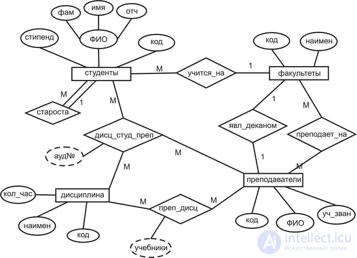
Fig. 2. Example of entity diagrams and relationships between them.
Speaking about the types of connections that can exist between entities of the domain (their examples are shown in Figure 4.2), we can note the following.
Between the same entities at the same time can take place not one, but several types of connections. For example, there are two connections between entities TEACHERS and FACULTIES: the connection is TEACHED_A and the connection is YDL_DECAN, reflecting respectively two facts: the first that teachers teach in certain faculties , and the second that some teachers are deans of faculties .
Instances of not only two different entities, but also instances of the same entity may be related to each other. For example, for specific students it may be indicated who their headman is (the headman is also a student).
More than two instances may be linked. entity types Thus, the DISC_STUD_PREP link reflects the fact that students learn specific academic disciplines from specific teachers. Moreover, it should be noted that in the general case this relationship is not equivalent to three connections of the form:
STUDENTS ↔ DISCIPLINES,
STUDENTS ↔ TEACHERS AND
TEACHERS ↔ DISCIPLINES.
Thus, depending on the number of related entities, the relationship can be single (this is the connection between instances of the same entity, it is also called reflexive ), binary (between two entities), ternary (between three entities) and, in general, nary (connection between n entities). It should be noted right away that in practice binary connections are most often used when modeling the subject area.
Важной характеристикой связи между экземплярами сущностей является степень ( cardinality ) этой связи. Степень связи характеризует число экземпляров сущности, которое может участвовать с каждой стороны связи. Для бинарных связей по степени связи с каждой ее стороны различают связи типов один-к-одному (1:1), один-ко-многим (1:m), многие-к-одному (m:1) и многие-ко-многим (m:n).
Рассмотрим эти варианты на примере связи между сущностями Преподаватель и Дисциплина. Эта связь указывает на то, какими преподавателями преподаются конкретные учебные дисциплины, и наоборот, какие дисциплины преподаются конкретными преподавателями.
1: 1 relationship (one-to-one). In this regard, not more than one instance of each of the entities to be bound can participate.
An example . Each teacher teaches no more than one discipline, and each discipline is taught by no more than one teacher.
Links 1: m (one-to-many) and m : 1 (many-to-one). No more than one instance of one entity can be associated with any number of instances of another entity.
Communication example 1: m . Each teacher can teach any number of disciplines, but each discipline is taught by no more than one teacher.
Connection example m : 1. Each teacher can teach no more than one academic discipline, but each discipline can be taught by more than one teacher.
The m : n relationship (many-to-many). Each of the instances of both entities can be associated with any number of instances of the other entity.
An example . Each teacher can teach any number of disciplines, and each discipline can be taught by any number of teachers.
On the ER-diagrams, the degree of communication may be indicated, for example, by the symbols 1 or m at the corresponding ends of the lines denoting a connection,

or using type designations

В обоих примерах изображена связь типа один-ко-многим (1:m) между сущностью Преподаватель и сущностью Дисциплина.
Другой важной характеристикой связи в каждом из рассмотренных выше случаев является так называемый класс принадлежности экземпляра сущности с одной стороны связи к экземплярам сущности на другой ее стороне. Этот класс может быть обязательным (mandatory) или необязательным.
Обязательный класс принадлежности сущности A к сущности B , означает, что каждый экземпляр сущности A обязательно должен быть связан с каким-либо экземпляром сущности B .
Необязательный класс принадлежности сущности A к сущности B , означает, что конкретный экземплярсущности A может быть связан с экземплярами сущности B , а может быть и не связан ни с одним из них.
Например, для связи сущности Преподаватель с сущностью Дисциплина может иметь место ситуация, когда:
Варианты принадлежности конкретных преподавателей (экземпляров сущности Преподаватель) к множеству учебных дисциплин, представленных сущностью Дисциплина, можно сформулировать и интерпретировать следующими образом.
Степень связи …-к-одному , принадлежность экземпляров сущности Преподаватель к экземплярам сущности Дисциплина относится к необязательному классу.
На ER-диаграммах обозначается как

Преподаватель принадлежит одной дисциплине или не принадлежит ни к одной дисциплине (связан с 0 или 1-й дисциплиной).
Степень связи …-к-одному , принадлежность экземпляров сущности Преподаватель к экземплярам сущности Дисциплина относится к обязательному классу.
На ER-диаграммах обозначается как

Преподаватель принадлежит одной и только одной дисциплине.
Степень связи …-ко-многим , принадлежность экземпляров сущности Преподаватель к экземплярам сущности Дисциплина относится к необязательному классу.
На ER-диаграммах обозначается как

Преподаватель может быть связан с любым числом дисциплин (от 0 до m ).
Степень связи …-ко-многим , принадлежность экземпляров сущности Преподаватель к экземплярам сущности Дисциплина и относится к обязательному классу.
На ER-диаграммах обозначается как

Преподаватель обязательно должен быть связан с одной или несколькими дисциплинами (от 1 до m ).
Examples
ER-диаграмма следующего вида
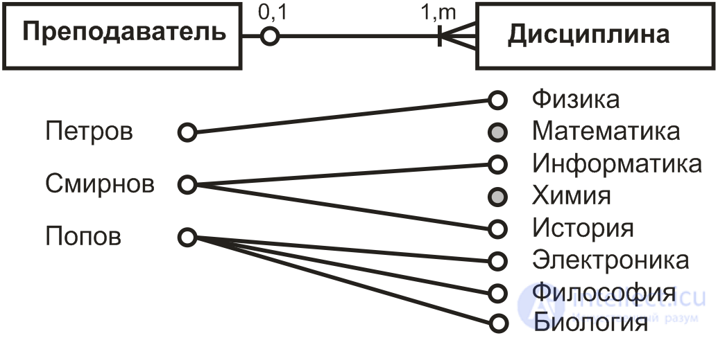
представляет связь сущности Преподаватель с сущностью Дисциплина степени один-ко-многим (1: m ) с обязательным классом принадлежности экземпляров сущности Преподаватель экземплярам сущностиДисциплина и необязательным классом принадлежности экземпляров сущности Дисциплина к экземплярамсущности Преподаватель. Это означает:
Следующая диаграмма
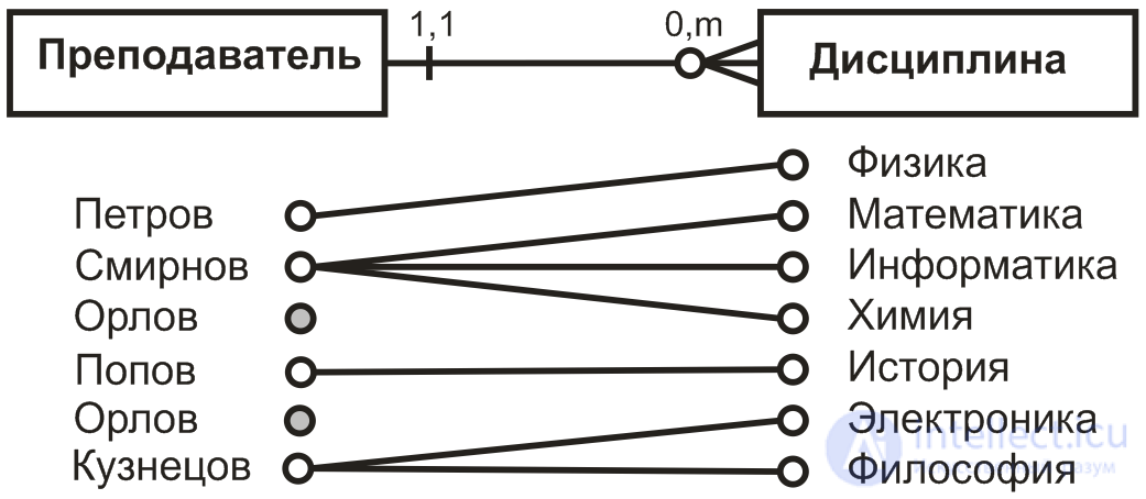
представляет связь сущности Преподаватель с сущностью Дисциплина степени один-ко-многим (1: m ) с необязательным классом принадлежности экземпляров сущности Преподаватель к экземплярам сущностиДисциплина и обязательным классом принадлежности экземпляров сущности Дисциплина экземплярамсущности Преподаватель. Это означает:
Как видно из вышеизложенного, построение модели предметной области на данном (инфологическом) этапе проектирования базы данных состоит в выделении в ней представляющих интерес для решаемой задачи сущностей , определении их свойств и связей между ними и построении на основе этого соответствующей ER‑диаграммы. Такая диаграмма позволяет в компактном виде представить информацию о предметной области, которая затем должна быть преобразована в схему проектируемой базы данных.
Следует обратить внимание на следующую проблему, возникающую при решении задачи описания предметной области в понятиях модели сущность-связь, то есть средствами ER-диаграмм. Проектировщику базы данных необходимо решить, какие элементы и характеристики предметной области должны быть представлены в модели в виде объектов-сущностей, какие в виде свойств этих сущностей, а какие в виде связей (отношений) между ними. Дело в том, что на самом деле отличие этих категорий друг от друга является не абсолютным, а условным. В частности, один и тот же объект предметной области в одних ситуациях может выступать как свойство другого объекта, а в других может быть представлен как самостоятельная сущность. Например, элемент Адрес может выступать в качестве свойства (атрибута)сущности Студент, а может рассматриваться как самостоятельный объект, обладающий своим набором свойств (Город, Улица, Дом, …) и связанный с сущностью Студент связью типа Проживает. Также условным является различие между категориями сущность и связь . Например, связь между сущностями Преподаватель и Дисциплина может при желании интерпретироваться и представляться как самостоятельная сущность(можно назвать ее Преподаваемая дисциплина), которая, в свою очередь, уже как сущность, может обладать какими-либо своими свойствами, например свойством Учебники, представляющим литературу, используемую преподавателем по учебной дисциплине.
Принимая во внимание сказанное, уточним определение категорий сущность ( объект ), свойство и связь следующим образом.
Под сущностью понимается конкретный опознаваемый предмет, элемент, единица (реальные или абстрактные), имеющие четко определенное функциональное назначение, четко определенные границы в данной предметной области, обусловленные контекстом задач, в рамках которых представляет интерес информация о данной предметной области.
Свойства выступают в качестве характеристик сущности, позволяя, в частности, выделять, идентифицировать данную сущность из множества других сущностей. При этом в качестве свойств сущности могут выступать другие сущности предметной области. И в этом случае представление сущности в форме совокупности (агрегации) ее свойств есть выражение в модели определенного отношения между сущностью-агрегацией и сущностями, выступающими в качестве ее свойств.
Связь – это категория, которая также используется для выражения некоторого отношения между сущностями, при этом, однако, связь как выражение отношения между двумя и более сущностями, можно рассматривать и как самостоятельную сущность, которая сама может обладать набором собственных свойств, не являющихся свойствами каждой из связываемых ею сущностей.
Забегая вперед, заметим, что в рассматриваемой ниже реляционной модели данных, как самостоятельные объекты предметной области, так и связи между ними представляются с помощью однотипных структур данных, а именно – реляционных таблиц-отношений . В последнем случае, когда такая таблица представляет связь между объектами, эти объекты обычно выступают в качестве атрибутов, образующих, составной ключ таблицы.
Решение вопросов определения и взаимоотношения категорий сущности , свойства , связи входит в задачу проектирования семантической ER-модели предметной области . Однако очень важно понимать необходимость как можно более точного определения границ предметной области именно на этапеинфологического проектирования базы данных. Дело в том, что от решения этого вопроса в большой степени зависят структуры и способы интерпретации данных при последующем построении концептуальной датологической модели данных, эффективность функционирования прикладных подсистем и возможность обслуживания ими запросов пользователей. Неправильное определение границ предметной области на начальном этапе проектирования базы данных может на более поздних этапах ее проектирования потребовать значительных усилий по изменениям структур данных и кодов интерпретирующих их программных средств или даже перепроектирования системы в целом.
Как уже было сказано выше, свойство – это категория, представляющая характеристики сущности. При этом одни свойства сущности позволяют идентифицировать ее, то есть выделять из множества других сущностей, другие свойства позволяют объединять множество экземпляров сущностей, обладающих общими свойствами, в абстрактные сущности – типы или классы .
Следует, однако, обратить внимание на то, что абстрактная категория свойство объединяет элементы, информационные единицы предметной области, также попадающие под определение категории сущность(нечто, идентифицируемое в предметной области). Проще говоря, свойства также являются одним из типов сущностей предметной области, и в этом смысле, как уже говорилось, представление некоторой сущности в форме агрегации других сущностей, выступающих в качестве ее свойств, является выражением одного из видов отношений между сущностями.
Определение сущности А, в виде агрегации
А{< свойство 1>, < свойство 2>, …, < свойство n>}
является ни чем иным, как выражением определенного отношения или связи между сущностями-свойствами и сущностью-носителем этих свойств.
В качестве примера рассмотрим в качестве примера сущность Студент, представляющую в модели множество студентов, являющихся ее экземплярами. Эта сущность представлена на рис. 3 агрегацией ее свойств {№ студенческого билета, Курс, ФИО, Дата рождения}.
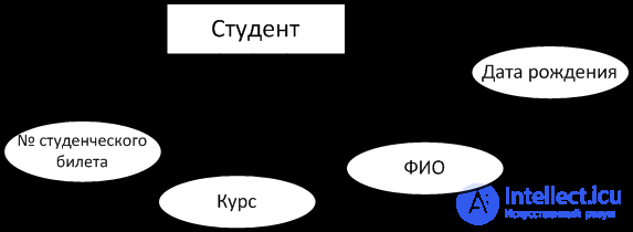
Fig. 3. Агрегация свойств сущности Студент
Если речь идет о свойствах, которые могут выступать в роли идентификаторов экземпляров сущности, то между такими свойствами и идентифицируемой ими сущности имеет место обязательная связь типа один-к-одному. В рассматриваемом примере в качестве свойства-идентификатора выступает свойство№ студенческого билета. Другие свойства сущности (неидентифицирующие) связаны с нею связью типа один-ко-многим . Например, свойство Курс – конкретный студент учится на одном конкретном курсе, но на конкретном курсе учится множество студентов. Классы принадлежности свойств с определяемой ими сущностью, также как и класс принадлежности самой сущности с определяющими ее свойствами являются обязательными . То есть, экземпляры сущности не могут существовать без соответствующих значений ее свойств, также как значения этих свойств не существуют отдельно от определяемых ими экземпляровсущности. Условную схему рис. 3 можно представить уже в более формализованном виде модели сущность-связь на рис. four.
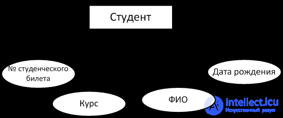
Fig. 4. ER-диаграмма сущности Студент с ее свойствами
Рассмотрим теперь ситуацию, когда в проектируемую схему нам необходимо ввести информацию о связи студентов с их научными руководителями. Для этого в схему нужно ввести новый объект-сущность Научный руководитель. Этот объект связан с сущностью Студент связью один-ко-многим , то есть у конкретного студента может быть один руководитель, а у руководителя может быть несколько руководимых им студентов.
Можно обратить внимание на сходство типа этой связи со связями сущности Студент с ее свойствами на рис. 3 (связь один-ко-многим ). Однако, при внимательном рассмотрении классов принадлежности сущностиСтудент и объекта Научный руководитель в их взаимной связи, можно увидеть, что объект Научный руководитель уже не может выступать в качестве свойства сущности Студент. Дело в том, что в нашем примере могут быть студенты, у которых еще нет научного руководителя, также, как и у конкретного преподавателя-руководителя может не быть студента для руководства. Выражаясь в понятиях ER-модели, класс принадлежности связи сущности к Научному руководителю и обратной связи Научный руководитель – Студент является необязательным , что отражено в условных обозначениях на схеме рис. five.

Fig. 4.5. ER-diagram of the connection of the entity Student with the essence Supervisor
In other words, the object of the Supervisor in the context of its connection with the essence The student no longer acts as a property of this entity, but as an independent entity , instances of which (specific leaders) can exist separately from instances of the Student entity (specific students). At the same time, in this new entity, the Supervisor in his further analysis of the subject area may already reveal his own properties (for example, full name, Academic title, etc.), as shown in Fig. 6
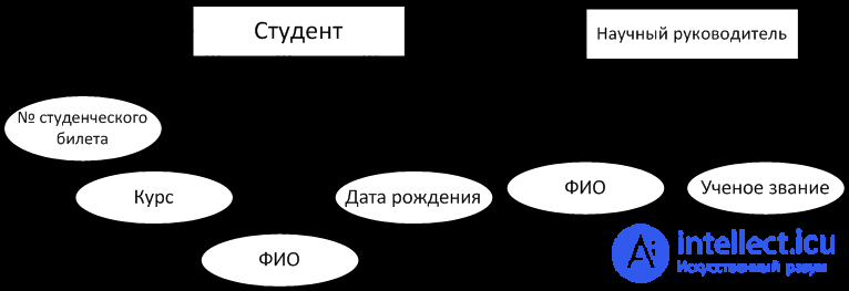
Fig. 6. Representation of the object The supervisor as an independent entity associated with the essence of the student
Given the above, deciding the question of when an object in an ER model can or should be represented as a property of an entity or, on the contrary, as an independent entity, one can proceed from the following considerations.
First, the object of the domain A can act as a property of the entity B in cases where the classes of belonging of object A to entity B and, conversely, entity B to object A are mandatory , in other words, instances of entity A and the value of object B cannot exist separately from each other.
In addition, as a property, objects of the simplest type (numeric or string literals) are usually used. A literal is usually called the simplest object-entity that identifies itself, any changes of which turn it into another object, for example, '01561', 'physics'.
For a compact display on the diagram of the essence of the Student and its properties (Fig. 4), the form shown in Fig. 2 is usually used. 7

Fig. 4.7. Representation of the essence Student with her properties
Bold type and / or underline usually distinguish properties whose values are unique for each instance of a given entity, i.e., which are identifiers of entity instances.
Consider a situation where between entities selected in the subject domain, simple or complex (which are aggregations of other entities that appear in the form of properties), there is a more complex many-to-many relationship. For example, the relationship between the Entity Student and Discipline consists in the fact that each student studies many disciplines, and each discipline is studied by many students (Fig. 8).

Fig. 8. Many-to-many relationship between Student and Discipline entities.
In this case, it is clear that none of these entities can act as a property of another entity in this pair, simply because there must be a many-to-one relationship between an entity and its property. It also shows that each of the entities Student and Discipline already has its own set of properties.
In the diagram, it is noted that the classes of belonging of both entities involved in the relationship are mandatory , that is, it is assumed that there may be students who are not related to any of the disciplines, and disciplines that are not associated with any of the students.
One can approach the consideration of the relationship between the entities Student and Discipline and the other. To consider this relationship as an independent entity of the subject area. You can, for example, call this essence of performance and present with it information about which student, in which discipline has a certain grade. This version of the ER-diagram is presented in Fig. 9.

Fig. 9. Representation of many-to-many relationships with the help of a new self-entity
It can be seen that the new entity, which was formed and introduced into the scheme, has its own properties (in the diagram it is Assessment and Date of Submission) and is associated with the entities Student and Discipline already with many-to-one connections.
At the same time, the entity and student discipline classes are essentially optional , that is, there may be students who have no grades and disciplines that have not been surrendered to anyone.
In turn, the class of belonging to the entity. Student performance to the entities. Student and Discipline is obligatory . This reflects the fact that an Entity cannot have instances unrelated to any student and any discipline.
The given example illustrates the possibility of an equivalent representation in the ER-model of a relationship between many-to-many type entities by introducing into the schema a new entity and replacing a many-to-many relationship with two many-to-one relationships.
Similarly, more complex types of relationships between entities can be represented in the entity-relationship model, for example, ternary and n- ary relations. In other words, complex types of relationships between entities can be reduced to simpler types of relationships in the ER model without losing information, which makes it possible to use simpler and more uniform data structures in the future on the datological stage of database design.
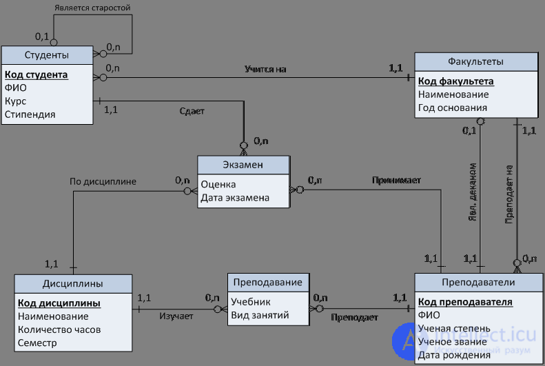
Fig. 10. ER-diagram of the subject area depicted in Fig. 2

Comments
To leave a comment
Databases, knowledge and data warehousing. Big data, DBMS and SQL and noSQL
Terms: Databases, knowledge and data warehousing. Big data, DBMS and SQL and noSQL