Lecture
Modeling the database structure using the normalization algorithm described in previous chapters has serious drawbacks:
In the actual design of the database structure, another method is used - the so-called semantic modeling . Semantic modeling is a modeling of the data structure, based on the meaning of this data. As a tool for semantic modeling, various variants of entity-relationship diagrams ( ER - Entity-Relationship ) are used.
The first version of the entity-relationship model was proposed in 1976 by Peter Pin-Sheng Chen [37]. In the future, many authors have developed their own versions of similar models (Martin notation, IDEF1X notation, Barker notation, etc.). In addition, various software tools that implement the same notation may differ in their capabilities. In fact, all variants of the entity-relationship diagrams are based on the same idea - the drawing is always more visual than the text description. All such diagrams use a graphical representation of the entities of the domain, their properties (attributes), and the relationships between the entities.
We will describe working with ER diagrams close to the Barker notation, as fairly easy to understand basic ideas. This chapter is more an illustration of semantic modeling methods than a full-fledged introduction to this area.
Definition 1 . An entity is a class of objects of the same type, information about which should be taken into account in the model.
Each entity must have a name expressed in the singular noun.
Examples of entities can be such classes of objects as "Supplier", "Employee", "Consignment note".
Each entity in the model is depicted as a rectangle with the name:
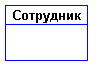
Fig. one
Definition 2 . An instance of an entity is a specific representative of that entity.
For example, a representative of the entity “Employee” may be “Employee Ivanov”.
Entity instances must be distinguishable , i.e. Entities must have some properties unique to each instance of this entity.
Definition 3 . An entity attribute is a named characteristic that is some property of an entity.
The name of the attribute should be expressed in the singular noun (possibly with characterizing adjectives).
Examples of attributes of the entity "Employee" can be such attributes as "Personnel Number", "Last Name", "First Name", "Middle Name", "Position", "Salary", etc.
Attributes are depicted within the rectangle defining the entity:

Fig. 2
Definition 4 . An entity key is a non-redundant set of attributes, the values of which in combination are unique for each entity instance. The redundancy lies in the fact that the removal of any attribute from the key violates its uniqueness.
An entity may have several different keys.
Key attributes are depicted in the diagram underlined:

Fig. 3
Definition 5 . Communication is some association between two entities. One entity may be associated with another entity or with itself.
Links allow one entity to find other entities associated with it.
For example, relationships between entities can be expressed by the following phrases - "EMPLOYEE can have several CHILDREN", "each EMPLOYEE must be registered in exactly one DEPARTMENT".
Graphically, the connection is represented by a line connecting two entities:
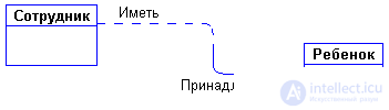
Fig. four
Each link has two ends and one or two names. The name is usually expressed in an indefinite verb form: "have", "belong", etc. Each of the names refers to its end connection. Sometimes names are not written because of their obviousness.
Each link can have one of the following types of link :

Fig. five
A one-to-one relationship means that one instance of the first entity (left) is associated with one instance of the second entity (right). The one-to-one relationship most often indicates that in fact we have only one entity, which is incorrectly divided into two.
A one-to-many relationship means that one instance of the first entity (left) is associated with several instances of the second entity (right). This is the most commonly used type of connection. The left entity (from the “one” side) is called the parent , the right (from the “many” side) - subsidiary . A typical example of such a link is shown in Fig. four.
A many-to-many relationship means that each instance of the first entity can be associated with several instances of the second entity, and each instance of the second entity can be associated with several instances of the first entity. A many-to-many communication type is a temporary communication type that is valid in the early stages of model development. In the future, this type of relationship should be replaced by two one-to-many relationships by creating an intermediate entity.
Each link can have one of two link modalities :

Fig. 6
The “ may ” modality means that an instance of one entity may be associated with one or more instances of another entity, or it may not be associated with any instance.
The “ must ” modality means that an instance of one entity must be associated with at least one instance of another entity.
A link can have different modalities from different ends (as in Fig. 4).
The described graphical syntax allows you to read diagrams unambiguously using the following phrasing scheme:
.
Each link can be read both from left to right and from right to left. The link in Fig. 4 reads like this:
From left to right: "every employee can have several children."
Right to left: "Every child must belong to exactly one employee."
When developing ER-models, we must obtain the following information about the subject area:
ER-diagrams are convenient because the process of selecting entities, attributes and relationships is iterative. Having developed the first approximate version of the diagrams, we refine them by interviewing domain experts. In this case, the documentation in which the results of conversations are recorded are the ER-diagrams themselves.
Suppose that we are faced with the task of developing an information system on the order of a wholesale trading company. First of all, we must study the subject area and the processes occurring in it. To do this, we interview employees of the company, read the documentation, study the forms of orders, invoices, etc.
For example, during a conversation with a sales manager, it turned out that he (the manager) believes that the system being designed should perform the following actions:
We will single out all the nouns in these sentences - these will be potential candidates for entities and attributes, and we will analyze them (we will highlight incomprehensible terms with a question mark):
Immediately there is an obvious link between entities - "buyers can buy a lot of goods" and "goods can be sold to many buyers." The first version of the diagram looks like this:
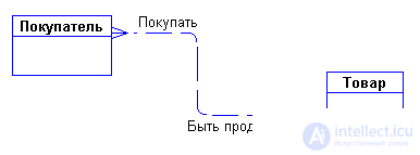
Fig. 7
After asking additional questions to the manager, we found out that the company has several warehouses. Moreover, each product can be stored in several warehouses and be sold from any warehouse.
Where can I put the entities “Consignment note” and “Warehouse” and with what to connect them? Let's ask ourselves how these entities are connected with each other and with the entities "Buyer" and "Goods"? Buyers buy goods, while receiving invoices, which include data on the quantity and price of the purchased goods. Each buyer can receive several invoices. Each invoice must write out to one buyer. Each invoice must contain several products (there are no empty invoices). Each product, in turn, can be sold to several buyers through several invoices. In addition, each invoice must be issued from a specific warehouse, and many invoices can be written from any warehouse. Thus, after clarification, the chart will look as follows:
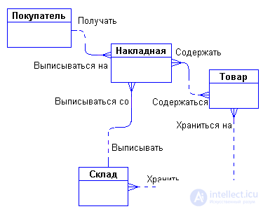
Fig. eight
It's time to think about the attributes of the entities. Speaking with employees of the company, we found out the following:
In the course of an additional conversation with the manager, we were able to clarify various concepts of prices. It turned out that each product has some current price. This is the price at which the item is being sold. Naturally, this price may change over time. The price of the same goods in different invoices issued at different times may be different. Thus, there are two prices - the price of the goods in the invoice and the current price of the goods.
With the emerging concept of “List of goods in the invoice” everything is pretty clear. Entities "Consignment note" and "Goods" are related to each other by a many-to-many relationship. Such a bond, as we noted earlier, should be split into two one-to-many bonds. This requires an additional entity. This entity will be the essence of the “List of goods in the invoice”. Its connection with the entities "Invoice" and "Goods" is characterized by the following phrases - "each invoice must have several entries from the list of goods in the invoice", "each entry from the list of goods in the invoice must be included in exactly one invoice", "each item can be included in several entries from the list of goods in the invoice "," each entry from the list of goods in the invoice must be associated with exactly one product ". The attributes "Quantity of goods in the consignment note" and "Price of goods in the consignment note" are attributes of the entity "List of goods in the invoice".
We will do the same with the link connecting the “Warehouse” and “Goods” entities. Let us introduce the additional entity "Goods in stock". The attribute of this entity will be "quantity of goods in stock". Thus, the product will be registered at any warehouse and its quantity at each warehouse will be different.
Now you can add all this to the diagram:
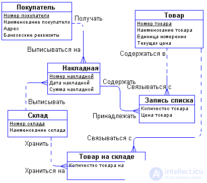
Fig. 9
The above developed ER diagram is an example of a conceptual diagram . This means that the diagram does not take into account the features of a particular DBMS. According to this conceptual diagram, you can build a physical diagram that will take into account such features of the DBMS as valid types and names of fields and tables, integrity constraints, etc. The physical version of the diagram in Fig. 9 may look, for example, as follows:
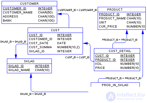
Fig. ten
In this diagram, each entity is a database table, each attribute becomes a column of the corresponding table. We draw attention to the fact that in many tables, for example, "CUST_DETAIL" and "PROD_IN_SKLAD", corresponding to the entities "Recording the invoice list" and "Goods in stock", new attributes appeared that were not in the conceptual model - these are the key attributes of the parent tables Migrated to child tables in order to provide a connection between the tables through foreign keys.
It is easy to see that the resulting tables are immediately in 3NF.
The real means of data modeling is not a formal method of normalizing relations, but the so-called semantic modeling .
As a tool for semantic modeling, various variants of entity-relationship diagrams ( ER - Entity-Relationship ) are used.
Entity-relationship diagrams let you use visual graphic symbols to model entities and their relationships.
Distinguish between conceptual and physical ER-diagrams. Conceptual diagrams do not take into account the features of specific DBMSs. Physical diagrams are based on conceptual and represent the prototype of a specific database. Entities defined in the conceptual diagram become tables, attributes become table columns (the data types and column names allowed for this DBMS are taken into account), connections are realized by migrating the key attributes of the parent entities and creating foreign keys.
With proper definition of entities, the resulting tables will immediately be in 3NF. The main advantage of the method is that the model is constructed by the method of sequential refinement of the original diagrams.
In this chapter, which is an illustration of ER-modeling methods, the more complex aspects of constructing diagrams are not considered, such as subtypes, roles, excluding connections, intolerable connections, identifying connections, etc.

Comments
To leave a comment
Databases, knowledge and data warehousing. Big data, DBMS and SQL and noSQL
Terms: Databases, knowledge and data warehousing. Big data, DBMS and SQL and noSQL