Lecture
The process of obtaining visual information by man
The human eye is a very thin device designed to receive and process all light information entering the eye.
In humans, an image is formed on the retina, followed by processing and writing it into memory in the brain.
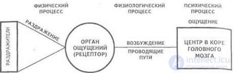
Figure 2 - The process of obtaining visual information by man
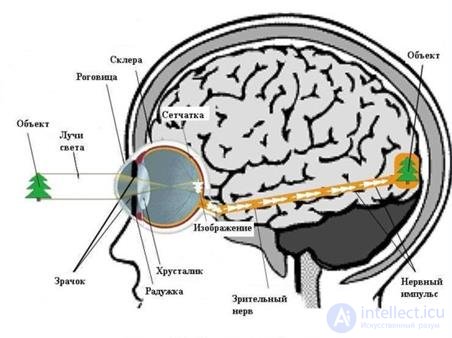
Figure 3 - Work of the human visual system
Visible light consists of the spectral distribution of electromagnetic energy with wavelengths in the range of 400-700 nm. Waves outside this range are called ultraviolet (UV) and infrared (IR). It is with perception that human processing of graphics, video and audio information begins. According to the theory of color vision, the color is perceived by receptors, the photosensitive retina of the eye with rods and cones capable of perceiving light of different wavelengths.
Three-component theory of Helmholtz. Color sensation provided by three types of flasks that are sensitive to one part of the spectrum (red, green, or blue).
Goering theory. In flasks there are substances sensitive to white-black, red-green and yellow-blue radiation.
Thus, a person in the process of processing visual information is able to distinguish the color, brightness, shape and size of objects visible to them.
At the same time, physical, physiological and mental processes take place and the eyes, the nervous system are involved, incl. brain.
The process of obtaining visual information by the computer vision system
Computer vision systems are in many ways reminiscent of the processing of visual information by humans, but have significant differences and their own characteristics, depending on the purpose of the system and its scope (Figure 4)

Figure 4 - Processes of processing visual information by man and computer
Computer vision systems
The implementation of computer vision systems is highly dependent on their field of application, hardware platform and performance requirements. Some systems are autonomous and solve specific problems of detection and measurement, while other systems comprise subsystems of larger systems, which may already contain mechanical manipulator control subsystems (robots), information databases (similar image search), man-machine interfaces and (computer games) etc. However, there are features typical of many computer vision systems (Figure 5).

Figure -5 Computer vision system processes
Acquisition of images: digital images are obtained from one or several image sensors, and which, in addition to various types of light-sensitive cameras, include distance sensors, radars, ultrasonic cameras, etc. Depending on the type of sensor, the resulting data can be a standard 2D image, 3D image or sequence of images. Pixel values usually correspond to the intensity of light in one or several spectral bands (color or images in shades of gray), but may be associated with various physical measurements, such as depth, absorption or reflection of sound or electromagnetic waves, or nuclear magnetic resonance.
Pre-processing: before computer vision techniques can be applied to video data in order to extract a certain amount of information, it is necessary to process the video data so that it satisfies certain conditions, depending on the method used. Examples are:
Re-sample to ensure that the image coordinate system is correct.
Noise removal in order to remove sensor distortions
Improved contrast, so that the right information can be detected
Scaling to better distinguish the structures in the image
Selection of details: details of the image of different levels of complexity are distinguished from video data. Typical examples of such parts are:
Lines, borders and edges
Localized points of interest, such as angles, drops, or dots: more complex details may relate to structure, shape, or movement.
Detection / Segmentation: at a certain stage of processing, it is decided which points or areas of the image are important for further processing. Examples are:
Selecting a specific set of points of interest
Segmentation of one or more image areas that contain a characteristic object.
High-level processing: in this step, the input data usually represents a small data set, for example, a set of points or an image region in which a certain object is supposed to be located. Examples are:
Check that the data satisfy the conditions depending on the method and application
Evaluation of characteristic parameters, such as the position or size of the object
Classification of the detected object in various categories
Features registration of visual information in the image processing system
The definition of the term “image” from the point of view of its processing and the main operations performed on it should be emphasized.
By image we mean the function of two real variables.  where I is the intensity (brightness) at the point with coordinates (x, y). Sometimes not the whole image will be processed, but some of it, which in English literature is called region-of-interest , ROI ( region of interest , PGI ).
For processing on a computer, the image must be sampled and quantized. The discretized and quantized image is called digital . The digital image A (m, n) is represented in a discrete two-dimensional space, where m is the row number and n is the column number. The element located at the intersection of the m-th row and the n-th column is called a pixel (picture element). Pixel intensity can be described as either real or integer. The relative intensity in real numbers usually varies from 0 to 1, and in whole numbers from 0 to 255.
Usually the physical signal arising at the point (xy) is a function dependent on many parameters (z is depth, λ is the wavelength, t is time). However we will
consider static, and more often monochromatic images.
PRESENTING IMAGES IN DIGITAL FORM
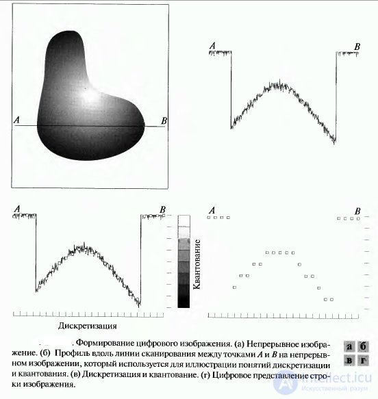
To implement digital image processing, it is necessary to convert a continuous (analog) image signal into a digital array. Such a conversion involves performing two transformations. The first transformation represents the replacement of a real continuous image by a set of samples at discrete points in time, such a transformation is called discretization. The second is the transformation of a continuous set of image signal values into a set of quantized values, such a conversion is called quantization (Figure 6).
Discretization of images.
Spatial discretization of the image involves the formation of a continuous function in discrete samples of spatial coordinates. Let the function fI ( x, y ) describe the original continuous image of infinite sizes. In an ideal image discretization system, spatial samples of the original
images are obtained by multiplying this function with a spatial discretizing function consisting of an infinite number of δ - Dirac functions defined in lattice sites with a step (Δ x, Δ y ):
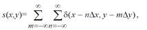
where m, n ∈ Z , Z is the set of integers
An inverse operation that allows a continuous image to be obtained from a digital array is called continuous image recovery. A continuous image can be obtained from samples of the function f ( x, y ) by linear spatial interpolation or by using a linear spatial filtering of a discretized image. sampling step should not exceed half
period of spatial harmonics corresponding to the smallest details of the image. If a
 then sampling
carried out with the frequency of Kotelnikov, twice the highest frequency of the spectrum of the original image. In cases where the spatial sampling frequency is selected in accordance with the Kotelnikov theorem, the original image can be accurately restored by spatially filtering the samples using the appropriate filter
Quantization of images.
To obtain a digital signal from a continuous signal, besides sampling by time, it is necessary to perform amplitude quantization. Quantization is that a signal with a continuous amplitude corresponds to a finite set of integer values of the signal proportional to the continuous signal.
value.
For this, the dynamic range of the signal f = [ fmin , fmax ] is split into a finite number of intervals — quantization intervals. Each interval is assigned a single value, called the quantization level, encoded by a binary code. All signal values falling within a certain interval are denoted by a single number defined for a given interval.
Optical sensors
Optical sensors are small-sized electronic devices that, under the influence of electromagnetic radiation in the visible, infrared and ultraviolet ranges, deliver a single or a set of signals to the input of a recording or control system. Optical sensors respond to opaque and translucent objects, water vapor, smoke, aerosols.
Optical sensors are a type of contactless sensors, since there is no mechanical contact between the sensitive area of the sensor (sensor) and the acting object. This property of optical sensors determines their widespread use in automated control systems. The range of optical sensors is much longer than other types of proximity sensors.
Optical sensors are also called optical proximity switches, photo sensors, photoelectric sensors.
Sensor emitter consists of: Case, Emitter, Trimmer, Generator, Indicator
Sensor receiver consists of: Case, Photodiode, Trimmer, Electronic key, Trigger, Demodulator, Indicator
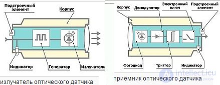
By type of device optical sensors are divided into monoblock and two-block. The monoblock radiator and receiver are in the same package. For two-block sensors, the radiation source and the optical signal receiver are located in separate housings.
According to the principle of operation, three groups of optical sensors are distinguished:
type T - barrier-type sensors (reception of a beam from a separate emitter)
type R - reflex-type sensors (receiving a beam reflected by a reflector)
type D - diffusion type sensors (reception of a beam, diffusely reflected by an object)
Principles of operation and device of CCD light receivers
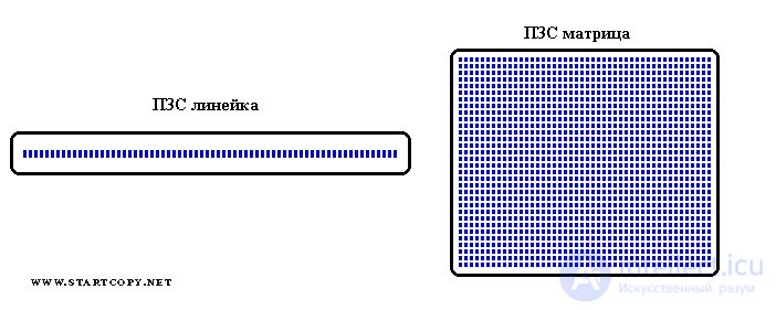
The arrangement of light-receiving elements (blue rectangles) in the CCD line-up and CCD-matrix.
The action of a CCD can be described as follows: each photosensitive element - a pixel - works like a piggy bank for electrons. Electrons appear in pixels under the action of light coming from the source. During a given interval of time, each pixel is gradually filled with electrons in proportion to the amount of light caught in it, like a bucket exposed to the street during a rain. At the end of this time, the electric charges accumulated by each pixel are in turn transmitted to the “output” of the device and measured. All this is possible due to the specific structure of the crystal, where the photosensitive elements are located, and the electrical control circuit.
The CCD also works in exactly the same way. After exposure (projection image illumination), the electronic control circuit of the device supplies it with a complex set of impulse voltages that begin to shift columns with electrons accumulated in pixels to the edge of the matrix, where there is a similar measuring CCD register, the charges in which are already shifted in the perpendicular direction and fall on the measuring element, creating in it signals proportional to the individual charges. Thus, for each subsequent point in time we can get the value of the accumulated charge and figure out which pixel on the matrix (row number and column number) it corresponds to.
Video camera
Video camera - the original value - a combination of television transmitting camera and video recorder. Subsequently, the word “video camera” practically supplanted the words “television camera” and “television camera” (TV camera), replacing them. For the first time the word "video camera" was used in relation to miniature hand-held cameras designed to record home video on a home video recorder. After the appearance of a combination of a transmitting TV camera and a video recorder - camcorders (eng. Camcorder), intended for television journalism (eng. Electronic news gathering), the word "camcorder" was included in professional use.
Camera hardware
As for the hardware component of a video camera device, here, as well as for cameras, the type of matrix used, the optical system (lens), the processor responsible for image and sound processing, camera power, display, stabilization system and much more matter.
ccd camcorder - camcorder device
For example, a video camera matrix. Only video cameras can use the system of three matrices at once, each of which is used to record its own color channel.
Light-sensitive arrays (sensors) are of two main types - CCD (CCD) and CMOS (CMOS).
1) CCD (Charge-Coupled Device) matrix - a memory chip sensitive to blue, red and green colors. Used in scanning technology as optical receivers. It is manufactured according to the technology of charge-coupled devices (CCD).
2) CMOS (Complementary Metal-Oxide-Semiconductor) matrix - photosensitive matrix, metal oxide semiconductor structure (CMOS) technology, sensor technology - converts light into electronic signals.
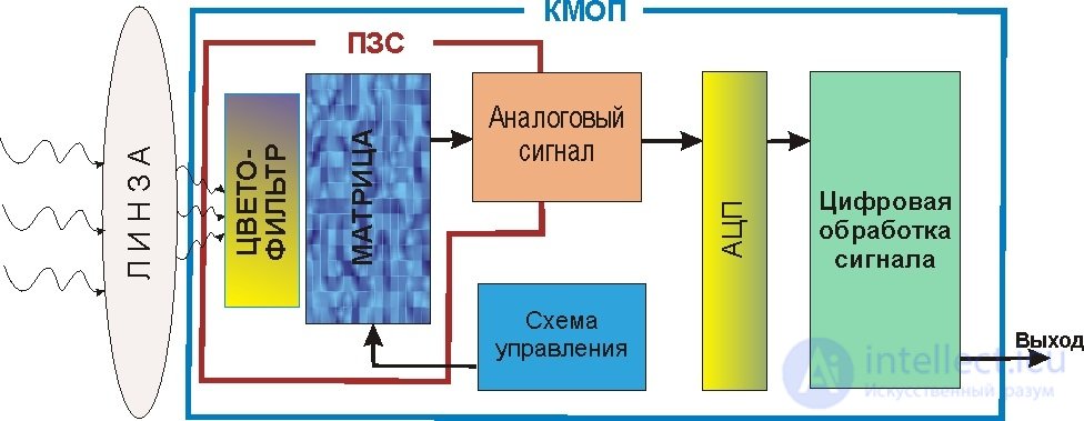
Fig. The block diagram of the CCD and CMOS.
CMOS matrixes are much cheaper than CCD matrices. On the basis of CMOS technology, sensors with a large number of megapixels can be made, and they will be inexpensive (compared to CCD). But CMOS-matrix noises do not give an image of the quality that cameras with CDD-matrices have.

Comments
To leave a comment
Methods and means of computer information technology
Terms: Methods and means of computer information technology