Lecture
Structural patterns address the question of how larger structures are formed from classes and objects. Structural patterns at the class level use inheritance to compose compositions from interfaces and implementations.
Title
Adapter (adapter), Wrapper (wrapper)
Task
Sometimes a class from the instrumental library cannot be used only because its interface does not correspond to the application being created. In some cases, we can change the interface to the desired one, but if we do not have the source code of the library, this solution is not suitable. Another option is to define another class in such a way that it will adapt the interface of one class to another interface.
The Adapter pattern converts the interface of one class to the interface of another that customers expect. The adapter ensures that classes work with incompatible interfaces, which would be impossible without it.
results
The first version of the pattern is called the object adapter, the second class adapter. The results of applying object and class adapters are slightly different.
Class adapter
Object Adapter
Structure
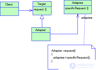
Figure 2.8 Structure of the Adapter pattern (object adapter)
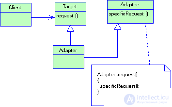
Figure 2.9 Adapter Pattern Structure (Class Adapter)
Title
Composite (linker)
Motivation
Applications such as graphic editors and electrical editors (diagrams allow users to build complex diagrams of simpler components.
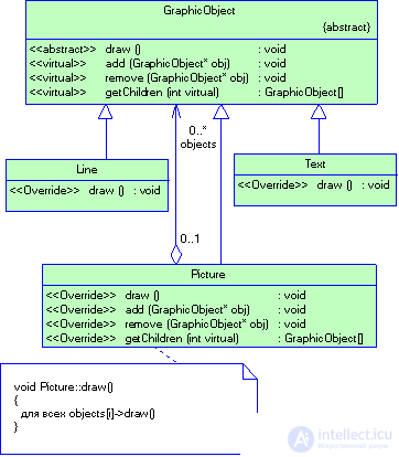
Figure 2.10 Composite pattern structure (example)
The designer can group smaller components to form larger ones, which, in turn, can be the basis for creating even larger ones. In a simple implementation, it would be acceptable to define classes of graphic primitives, such as text and lines, as well as classes that act as containers for these primitives. But such a solution has a significant drawback. The program in which these classes are used must deal differently with primitives and containers, although the user most often works with them uniformly. The need to distinguish between these objects complicates the application. The linker pattern describes how a recursive composition can be applied in such a way that the client does not have to distinguish between simple and composite objects. An example of the application of the template can be seen in Fig. 2.10.
The key to the linker pattern is an abstract class that represents both primitives and containers at the same time. In a graphics system, this class may be called Graphic. It declares operations specific. For each type of graphic object (such as Draw) and common to all composite objects, for example, operations for accessing and managing children. Subclasses Line, Rectangle and Text (see diagram above) define primitive graphic objects. In them, the operation Draw is implemented respectively for drawing straight lines, rectangles and text. Since primitive objects have no descendants, none of these subclasses implements operations related to managing descendants. The Picture class defines an aggregate consisting of Graphic objects. The operation Draw implemented in it calls the same function for each Descendant, and operations for working with descendants are no longer empty. Since the interface of the Picture Class corresponds to the Graphic interface, the Picture object may include other similar objects. The diagram below shows the typical structure of a composite object recursively composed of objects of the Graphic class.
Thus, it is possible to formulate the task for which the pattern is intended. The linker assembles objects into tree structures to represent a part-whole hierarchy. Allows customers to consistently treat individual and composite objects.
Structure
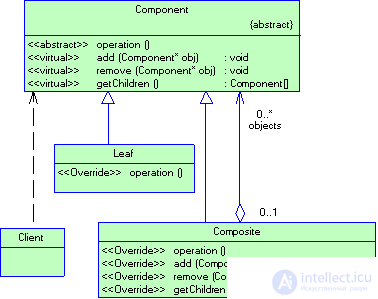
Figure 2.11 Composite Pattern Structure
results
Title
Decorator (decorator)
Tasks
Sometimes it is necessary to impose additional responsibilities on a separate object, and not on the class as a whole. Thus, a library for building graphical user interfaces must be able to add a new property, say, a frame or a new behavior (for example, the ability to scroll to any element of an interface). Add new responsibilities are permissible through inheritance. When inheriting from a class with a frame around each instance of a subclass, a frame will be drawn. However, this solution is static, and therefore not flexible enough. The client can not control the design of the component frame. A more flexible approach is another: place the component in another object, called the decorator, which adds a frame. The decorator follows the interface of the object being decorated, therefore its presence is transparent to the component's clients. The decorator redirects requests to the internal component, but can also perform additional actions (for example, draw a frame) before or after the redirection. Since decorators are transparent, they can invest in each other, thereby adding any number of new responsibilities.
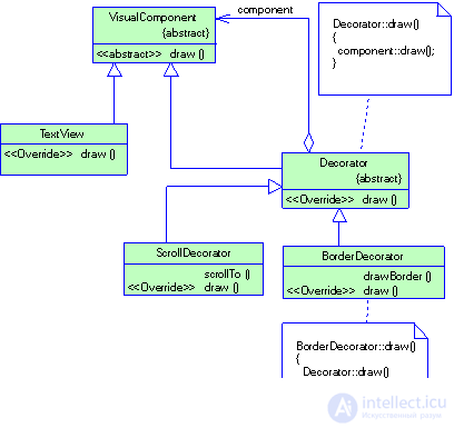
Figure 2.12 Decorator Pattern Structure (example)
Suppose there is an object of the TextView class that displays text in a window. By default, the TextView does not have scroll bars, as they are not always needed. But if necessary, they can be added using the ScrollDecorator decorator. Suppose we also want to add a bold solid frame around the TextView object. Here can help BorderDecorator decorator. The diagram below shows how the composition of a TextView object with BorderDecorator and ScrollDecorator objects produces an element for entering text, surrounded by a frame and provided with a scroll bar.
The ScrollDecorator and BorderDecorator classes are subclasses of Decorator, an abstract class that represents visual components used to style other visual components. VisualComponent is an abstract class for representing visual objects. It defines an interface for drawing and handling events. Note that the Decorator class simply forwards drawing requests to its component, and its subclasses can extend this operation (see Figure 2.13).
Structure
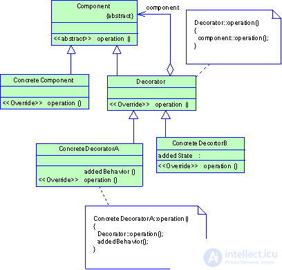
Figure 2.13 Structure of the Decorator pattern
results
The decorator pattern has at least two pluses and two minuses:
Title
Facade
Purpose
Provides a unified interface instead of a set of interfaces of a certain subsystem. The facade defines a higher level interface that simplifies the use of the subsystem.
Splitting into subsystems facilitates the design of a complex system as a whole. The overall goal of any design is to minimize the dependence of the subsystems on each other and the exchange of information between them. One of the ways to solve this problem is to introduce an object facade, which provides a single simplified interface to more complex system tools.
Structure
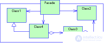
Figure 2.14 Structure of the Facade Pattern
Members
Facade - facade. Knows which classes of the subsystem to address the request; delegates client requests to relevant objects within the subsystem;
Subsystem Classes. Implement the functionality of the subsystem; perform the work assigned by the Facade object; they do not “know” anything about the existence of the facade, that is, they do not store references to it.
Relations
Clients communicate with the subsystem by sending requests to the facade. It redirects them to suitable objects within the subsystem. Although it is the objects of the subsystem that do the main work, the facade may have to convert its Interface to the subsystem interfaces. Clients using the facade do not have direct access to the objects of the subsystem.
results
The facade pattern has the following advantages:
Title
Low Coupling
Problem
The degree of coupling (coupling) is a measure that determines how rigidly one element is associated with other elements, or how much data about other elements it possesses. An element with a low degree of connectivity (or weak binding) depends on a not very large number of other elements. The expression "very much" depends on the context, but it is necessary to evaluate it.
A class with a high degree of connectedness (or rigidly connected) depends on many other classes. However, the presence of such classes is undesirable because it leads to the following problems.
Decision
Distribute responsibilities in such a way that the degree of connectedness remains low.
results
Example
Let the system have classes Payment, Sale and Register. Suppose you need to create an instance of the Payment class and associate it with the Sale object. Which class should be responsible for performing this operation? Since in the real domain the registration of the Payment object is performed by a Register object, according to the Creator template, the Register object is a good candidate for creating a Payment object. Then an instance of the Register object must pass the message addPayment to the Sale object, specifying a new Payment object as a parameter. The above reasoning is reflected in the fragment of the interaction diagram shown in Fig. 2.15.This distribution of responsibilities implies THAT class Register has knowledge of Payment class data (i.e. associated with it) .
Pay attention to the notation adopted in the language UML. The instance of the Payment object is given the explicit name p so that it can be used as a parameter to message 2.
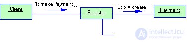
Figure 2.15 Interaction diagram. Strong connectivity
An alternative way to create a Payment object and associate it with a Sale object is to assign the responsibility for creating a Payment object to the Sale (Fig. 2.16)
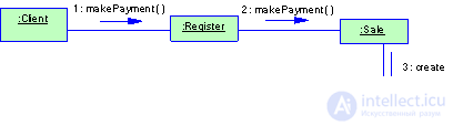
Figure 2.16 Interaction diagram. Weak connectivity
When not to use a pattern
A high degree of binding to resistant elements is not a problem. For example, a J2EE application can be tightly associated with Java libraries (java.util, etc.), since these libraries are widely distributed and stable.
Choose your game
A high degree of binding is not a problem in itself. The problem is tight coupling with unstable in some respects elements.
It is important to understand the following. A developer can provide program flexibility, implement the principle of encapsulation, and adhere to the principle of weak coupling in many aspects of the system. However, without convincing motivation, one should not at all costs fight to reduce the degree of binding of objects. Developers should choose “their game” to reduce binding and provide encapsulation. Special attention should be paid to unstable or rapidly changing elements.
Title
Information Expert
Problem
What is the most general principle of the distribution of responsibilities between objects in object-oriented design?
В модели системы могут быть определены десятки или сотни программных классов, а в приложении может потребоваться выполнение сотен или тысяч обязанностей. Во время объектно-ориентированного проектирования при формулировке принципов взаимодействия объектов необходимо распределить обязанности между классами.
При правильном выполнении этой задачи система становится гораздо проще для понимания, поддержки и расширения. Кроме того, появляется возможность повторного использования уже разработанных компонентов в последующих приложениях.
Decision
Назначить обязанность информационному эксперту — классу, у которого имеется информация, требуемая для выполнения обязанности.
results
The corresponding behavior of the system is provided by several classes containing the required information. This leads to class definitions that are much easier to understand and maintain. In addition, the High Cohesion template is supported.
Example
In the application, some class needs to know the total amount of the sale. Begin the distribution of responsibilities with their clear wording. From this point of view, we can formulate the following statement.
Which class should be responsible for knowing the total amount of the sale?
According to the Information Expert pattern, you need to determine which classes of objects contain the information necessary to calculate the total amount.
Теперь возникает ключевой вопрос: на основе какой модели нужно анализировать информацию - модели предметной области или проектирования? Модель предметной области иллюстрирует концептуальные классы из предметной области системы, а в модели проектирования показаны программные классы.
Ответ на этот вопрос сводится к следующему:
Если в модели проектирования имеются соответствующие классы, в первую очередь, следует использовать ее.
В противном случае нужно обратиться к модели предметной области и постараться уточнить ее для облегчения создания соответствующих программных классов.
Например, предположим, мы находимся в самом начале этапа проектирования, когда модель проектирования представлена в минимальном объеме. Следовательно, кандидатуру на роль информационного эксперта следует искать в модели предметной области. Вероятно, на эту роль подойдет концептуальный класс Sale. Тогда в модель проектирования нужно добавить соответствующий программный класс под именем Sale и присвоить ему обязанность вычисления общей стоимости, реализуемую с помощью вызова метода getTotal. При таком подходе сокращается разрыв между организацией программных объектов и соответствующих им понятий из предметной области.
Чтобы рассмотреть этот пример подробнее, обратимся к фрагменту модели предметной области, представленному на рис. 2.17.
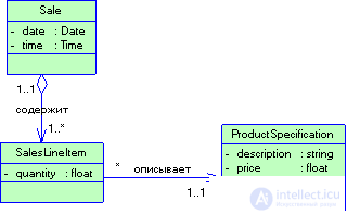
Рисунок 2.17 Фрагмент модели предметной области
Какая информация требуется для вычисления общей суммы? Необходимо узнать стоимость всех проданных товаров SalesLineltem и просуммировать эти промежуточные суммы. Такой информацией обладает лишь экземпляр объекта Sale. Следовательно, с точки зрения шаблона Information Expert объект Sale v подходит для выполнения этой обязанности, т.е. является информационным экспертом (information expert).
Как уже упоминалось, подобные вопросы распределения обязанностей зачастую возникают при создании диаграмм взаимодействий. Представьте, что вы приступили к работе, начав создание диаграмм для распределения обязанностей между объектами. Принятые решения иллюстрируются на фрагменте диаграммы Взаимодействий, представленном на рис. 2.18.
Однако на данном этапе выполнена не вся работа. Какая информация требуется для вычисления промежуточной суммы элементов продажи? Необходимы значения атрибутов SalesLineltem.quantity и SalesLineltem.price. Объекту SalesLineltem известно количество товара и известен связанный с ним объект ProductSpecif ication. Следовательно, в соответствии с шаблоном Expert, промежуточную сумму должен вычислять объект SalesLineltem. Другими словами, этот объект является информационным экспертом.
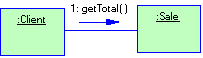
Рисунок 2.18 Распределение обязанностей в соответствии с паттерном Information Expert
В терминах диаграмм взаимодействий это означает, что объект Sale должен передать сообщения getSubtotal каждому объекту SalesLineltem, а затем просуммировать полученные результаты. Этот процесс проиллюстрирован на рис. 2.19
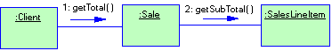
Рисунок 2.19 Распределение обязанностей в соответствии с паттерном Information Expert
Для выполнения обязанности, связанной со знанием и предоставлением промежуточной суммы, объекту SalesLineltem должна быть известна стоимость товара. В данном случае в качестве информационного эксперта будет выступать объект ProductSpecification (рис. 2.20).
В завершение можно сказать следующее. Для выполнения обязанности "знать и предоставлять общую сумму продажи трем объектам классов" были следующим образом присвоены три обязанности:
Рассмотрение и распределение обязанностей выполнялись в процессе создания диаграммы взаимодействий. Затем полученные результаты могут быть реализованы в разделе методов диаграммы классов. При назначении обязанностей, согласно шаблону Expert, был применен следующий принцип: обязанности связываются с тем объектом, который имеет информацию, необходимую для их выполнения.
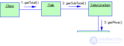
Рисунок 2.20 Распределение обязанностей в соответствии с паттерном Information Expert

Comments
To leave a comment
Object oriented programming
Terms: Object oriented programming