Lecture
The class diagram shows the classes and their relationships, thereby representing the logical aspect of the project. A separate class diagram represents a specific view of the class structure. At the analysis stage, we use class diagrams to highlight the common roles and responsibilities of entities that provide the required system behavior. At the design stage, we use the class diagram to convey the structure of the classes that form the system architecture.
The two main elements of a class diagram are classes and their main relationships.
Classes. In fig. Figure 5-2 shows the symbol for class representation in a diagram. A class is usually represented by an amorphous object, like a cloud [The selection of graphic notation is a difficult task. It is necessary to carefully balance between expressiveness and simplicity, so designing icons is to a large extent an art, not a science. We took a speech bubble from the materials of Intel Corporation, which documented its original object-oriented architecture iAPX432 [6]. The shape of this image hints at the vagueness of the boundaries of abstraction, from which smoothness and simplicity are not expected. The dotted contour symbolizes that customers usually operate with instances of this class, and not with the class itself. You can replace this shape with a rectangle, as did Rumbach [7]:

However, although the rectangle is easier to draw, this symbol is too often used in different situations and, therefore, does not cause associations. In addition, the designation of classes adopted by Rumbach is usual rectangles, while objects with rectangles with rounded corners conflict with other elements of its notation (rectangles for actors in data flow diagrams and rounded rectangles for states in transition diagrams). The cloud is also more convenient for marking the labels that, as we will see later, are needed for abstract and parameterized classes, and therefore it is preferable in class and object diagrams. The argument for the simplicity of drawing rectangles is controversial when using automated support for the notation system. But in order to preserve the possibility of simple drawing and emphasize the connection with the Rumbach method, we leave its notation for classes and objects as a valid alternative].
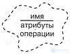
Fig. 5-2. Class icon.
On some class icons, it is useful to list several attributes and operations of a class. “On some,” because for most trivial classes it is troublesome and unnecessary. Attributes and operations on the diagram represent the prototype of the complete specification of the class in which all its elements are declared. If we want to see more class attributes on the diagram, we can increase the icon; if we don’t want to see them at all, we remove the dividing line and write only the name of the class.
As we described in Chapter 3, an attribute denotes a part of a compound object, or an aggregate. Attributes are used in analysis and design to express individual properties of a class [More precisely, an attribute is equivalent to an aggregation relation with a physical inclusion, the label of which coincides with the name of the attribute, and the power is exactly one]. We use the following language-independent syntax, in which an attribute can be indicated by a name or class, or both, and possibly have a default value:
The attribute name must be explicitly in the class context. Chapter 3 said that an operation is a service provided by a class. Operations are usually depicted inside the class icon only by their name. To distinguish them from attributes, brackets are added to their names. Sometimes it is useful to specify the full signature of the operation:
Operation names must be understood in the context of a class unambiguously in accordance with the rules for overloading operations of the selected implementation language.
General notation: the syntax of elements, such as attributes and operations, can be adapted to the syntax of the selected programming language. For example, in C ++ we can declare some attributes as static, or some operations as virtual or purely virtual [In C ++, members common to all objects of a class are declared static; virtual called polymorphic operation; purely virtual is called an operation, for the implementation of which the subclass is responsible]; in CLOS, we can mark the operation as a method : around . In any case, we use the specifics of the syntax of the language to denote the details. As described in Chapter 3, an abstract class is a class that cannot have instances. Since abstract classes are very important for designing a good class structure, we introduce for them a special triangular-shaped icon with the letter A in the middle, placed inside the class icon (Figure 5-3). General principle: jewelry represents secondary information about an entity in the system. All similar types of jewelry have the same type of nested triangle.
Relationship between classes. Classes are rarely isolated; on the contrary, as explained in chapter 3, they enter into relationships with each other. The types of relationships are shown in Fig. 5-4: association, inheritance, aggregation (has) and usage. When depicting a specific connection, it can be associated with a text label documenting the name of this connection or suggesting its role. The link name does not have to be global, but must be unique in its context.
The association icon connects the two classes and indicates the presence of a semantic link between them. Associations are often marked by nouns, such as Employment , describing the nature of communication. A class may have an association with itself (the so-called reflexive association). One pair of classes can have more than one associative relationship. Near the association icon you can indicate its power (see chapter 3) using the syntax of the following examples:
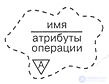
Fig. 5-3. Abstract class icon.
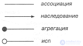
Fig. 5-4. Icons of relationships between classes.
The power designation is written at the end of the association line and means the number of links between each class instance at the beginning of the line with class instances at its end. If the power is not explicitly indicated, it is assumed that it is not defined.
The designations of the remaining three types of communication clarify the association pattern with additional notes. This is convenient, as in the process of developing a project, communications tend to be refined. First, we declare a semantic link between the two classes, and then, after making tactical decisions about their true relationship, we specify this link as inheritance, aggregation, or use.
The inheritance icon representing the total / particular relationship looks like an association icon with an arrow that points from subclass to superclass. In accordance with the rules of the chosen implementation language, the subclass inherits the structure and behavior of its superclass. A class can have one (single inheritance), or several (multiple inheritance) superclasses. Name conflicts between superclasses are resolved according to the rules of the selected language. As a rule, cycles in inheritance are prohibited. The power icon is not assigned to inheritance.
The aggregation icon denotes an integer / part relationship (a "has" relationship) and is obtained from the association icon by adding a filled circle at the end that represents an aggregate. Instances of a class at the other end of the arrow will in a sense be parts of instances of an aggregate class. Reflexive and cyclic aggregation is allowed. Aggregation does not require the physical inclusion of the part in the whole.
The use mark indicates the client / server relationship and is depicted as an association with an empty circle at the end corresponding to the client. This connection means that the client needs server services, that is, operations of the client class cause server class operations or have a signature in which the return value or arguments belong to the server class.
Example. The icons described above represent the most important elements of all class diagrams. Together, they provide the developer with a set of symbols sufficient to describe the foundation of the structure of the system classes.
Fig. Figures 5-5 show how the maintenance task of a greenhouse hydroponic system is described in these designations. This diagram represents only a small part of the system class structure. Here we see the GardeningPlan class (cultivation plan), which has an attribute called crop , one execute modifier operation and one canHarvest selector operation (can we collect?). There is an association between this class and the EnvironmentalController class (growing environment controller): plan instances define the climate that the controller instances must support.
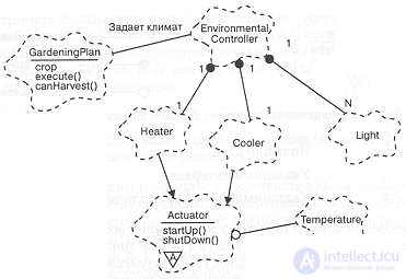
Fig. 5-5. Diagram of classes of hydroponic system.
This diagram also shows that the EnvironmentalController class is an aggregate: its instances contain exactly one instance of the classes Heater (heater) and Cooler (cooling device), and any number of instances of class Light (light bulb). Both the Heater and Cooler classes are subclasses of the abstract start-up process class of the Actuator class, which provides the startUp and shutDown protocols (start and stop, respectively), and which uses the class Temperature .
Each class must have a name; if the name is too long, you can shorten it or enlarge the icon in the diagram itself. The name of each class must be unique in the category containing it. For some languages, especially for C ++ and Smalltalk, we must require that each class has a name that is unique in the system.
As explained in chapter 3, class is a necessary but insufficient means of decomposition. When the system grows to a dozen classes, you can see groups of classes that are connected inside, and weakly engaged with others. We call such groups categories of classes .
Many object-oriented languages do not support this concept. Therefore, highlighting the notation for class categories makes it possible to express important architectural elements that could not be directly written in the implementation language [Smalltalk programming environment supports the concept of class categories. Actually, this prompted us to include categories in the notation. However, in Smalltalk, class categories have no semantic content: they exist only for more convenient organization of the class library. In C ++, categories of classes are associated with the concept of components (Straustrup), they are not yet a feature of the language, although the inclusion of namespace semantics is considered [8]. (Currently, namespaces are included in the standard. - Ed. Note)].

Fig. 5-6. Class category icon.
Classes and classes of classes can coexist on the same diagram. The upper levels of the logical architecture of large systems are usually described by several diagrams containing only categories of classes.
Categories of classes. Categories of classes are used to divide the logical model of the system. A class category is an aggregate consisting of classes and other categories of classes, in the same sense that a class is an aggregate consisting of operations and other classes. Each system class must "live" in a single category or be at the topmost level of the system. Unlike a class, the category of classes has no operations or states explicitly; they are contained therein implicitly in the descriptions of the aggregated classes.
In fig. Figures 5-6 show the category category. As for a class, a category requires a name that must be unique in the model and different from the class names.
It is sometimes useful to list some of the classes in the category icon. “Some”, because often the categories contain quite a few classes, and it would be troublesome to list them all, and this is not necessary. As well as the list of attributes and operations on the class icon, the list of classes in the category icon represents an abbreviated view of its specification. If we want to see in the category badge more classes, we can increase it. You can delete the dividing line and leave only the category name in the icon.
The class category is an encapsulated namespace. Similar to the qualification of names in C ++, the category name can be used to uniquely qualify the names of the classes and categories contained in it. For example, if a class A is given from category B , then its full name will be A :: B. Thus, as will be discussed further below, for nested categories the qualification of names extends to an arbitrary depth.
Some classes in a category may be open, that is, exported for use outside the category. The remaining classes can be part of the implementation, that is, not be used by any classes external to this category. For the analysis and design of the architecture, this distinction is very important, as it allows for the division of responsibilities between exported classes, which take over communication with customers, and internal classes into categories that actually do the work. In fact, during the analysis, closed aspects of the category of classes can be omitted. By default, all classes in a category are defined as open, unless explicitly stated otherwise. Access restrictions will be discussed below.
A category can use non-nested categories and classes. On the other hand, classes can use categories. For consistency, we denote these export-import relations in the same way as the usage relationship between classes (see Figure 5-4). For example, if category A uses category B , this means that classes from A can be descendants, or contain instances, use or still be somehow associated with classes from B.
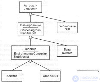
Fig. 5-7. Class diagram of the top level for the hydroponic system.
When there are too many generic classes in a category, like base container classes or other base classes like Object in Smalltalk, there are practical difficulties. Such classes will be used by almost all the other categories, cluttering up the root level of the diagram. To get out of the situation, such categories are marked with the global keyword in the lower left corner of the icon, indicating that the default category can be used by everyone else.
Top-level class diagrams, containing only categories of classes, represent the system architecture in the most general form. Such diagrams are extremely useful for visualizing layers and sections of a system. A layer denotes a set of categories of classes of one level of abstraction. Thus, layers represent a set of categories of classes, just like categories of classes are clusters of classes. Layers are usually needed to isolate the upper levels of abstraction from the lower. Sections designate related (in any way) categories of classes at different levels of abstraction. In this sense, the layers are horizontal sections of the system, and the sections are vertical.
Example. In fig. Table 5-7 shows an example of a top-level class diagram for a greenhouse. This is a typical multilayer system. Here, abstractions that are closer to reality (namely, activators and sensors of climate and fertilizers) are located at the lowest levels, and abstractions reflecting the concepts of the user are closer to the top. The category of Crop Types is global, that is, its services are available to all other categories. The class category planning icon shows two of its important classes: GardeningPlan (cultivation plan) from Fig. 5-5 and PlanAnalyst (plan analyzer). Increasing any of the eight categories of classes shown in the figure will reveal their constituent classes.
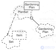
Fig. 5-8. The icon of the parameterized class.
So far, we have dealt with a substantial part of our notation [All the essential elements in the aggregate form the Booch Lite notation]. However, in order to convey some frequently occurring strategic and tactical decisions, we will need to expand it. The general rule is: keep to the essential concepts and notation, and apply additional ones only when they are really necessary.
Parameterized Classes. In some object-oriented programming languages, such as C ++, Eiffel and Ada, you can create parameterized classes. As mentioned in Chapter 3, a parameterized class is a family of classes with a common structure and behavior. To create a specific class of this family, you need to substitute actual parameters (process of instantiation) instead of formal parameters. A specific class can spawn instances.
Параметризованные классы достаточно сильно отличаются от обычных, что отмечается специальным украшением на их значках. Как показывает пример на рис. 5-8, параметризованный класс изображается значком обычного класса с пунктирным прямоугольником в правом верхнем углу, в котором указаны параметры. Инстанцированный класс изображается обычным значком класса с украшением в виде прямоугольника (со сплошной границей) с перечисленными в нем фактическими параметрами.
Связь между параметризованным классом и его инстанцированием изображается пунктирной линией, указывающей на параметризованный класс. Для получения инстанцированного класса необходим другой конкретный класс как фактический параметр (GardeningPlan в этом примере).
Параметризованный класс не может порождать экземпляры и не может использоваться сам в качестве параметра. Каждый инстанцированный класс является новым классом, отличающимся от других конкретных классов того же семейства.
Метаклассы. В некоторых языках, таких как Smalltalk и CLOS, есть метаклассы. Метакласс (см. главу 3) - это класс класса. В Smalltalk, например, метаклассы - это механизм поддержки переменных и операций класса (подобных статическим членам класса в C++), особенно фабрик класса (производящих операций), создающих экземпляры объектов данного класса. В CLOS метаклассы играют важную роль в возможности уточнения семантики языка [9].
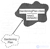
Fig. 5-9. Значок метакласса.
Метаклассы принципиально отличаются от обычных классов, и, чтобы подчеркнуть это, их значок закрашивается серым цветом, как это сделано на рис. 5-9. Связь между классом и его метаклассом (метасвязь) имеет вид жирной стрелки, направленной от класса к его метаклассу. Метакласс GardeningPlan обеспечивает методы-фабрики new() и default() , которые создают новые экземпляры класса GardeningPlan .
Метакласс не имеет экземпляров, но может любым образом быть ассоциирован с другими классами.
Metasvyaz has another application. On some class diagrams, it is useful to specify an object that is a static member of a certain class. To show the class of this object, we can hold the "object / class" meta link. This is consistent with the previous use: the relationship between some entity (object or class) and its class.
Утилиты классов. Благодаря своему происхождению, гибридные языки, такие как C++, Object Pascal и CLOS, позволяют разработчику применять как процедурный, так и объектно-ориентированный стиль программирования. Это контрастирует со Smalltalk, который целиком организован вокруг классов. В гибридном языке есть возможность описать функцию-не-член, называемую также свободной подпрограммой . Свободные подпрограммы часто возникают во время анализа и проектирования на границе объектно-ориентированной системы и ее процедурного интерфейса с внешним миром.
Utilities classes are used in one of two ways. First, class utilities can contain one or more free subroutines, and then simply list the logical groups of such non-member functions. Second, class utilities can denote a class that has only class variables (and operations) (in C ++, this would mean a class with only static elements [Smalltalk programmers often use the idiom of utilities to achieve the same effect]). It makes no sense for such classes to have instances, because all instances will be in the same state. Such a class itself acts as its only instance.
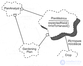
Fig. 5-10. Class utility icon.
Как показано на рис. 5-10, утилита классов обозначается обычным значком класса с украшением в виде тени. В этом примере утилита классов PlanMetrics (параметры плана) предоставляет две важные операции: expectedYield (ожидаемый урожай) и timeToHarvest (время сбора урожая). Утилита обеспечивает эти две операции на основе услуг, предоставляемых классами нижнего уровня - GardeningPlan (план) и CropDatabase (база данных об урожае). Как показывает диаграмма, PlanMetrics зависит от CropDatabase : получает от нее информацию об истории посевов. В свою очередь, класс PlanAnalyst использует услуги PlanHetrics .
Fig. 5-10 иллюстрирует обычное использование утилит классов: здесь утилита предоставляет услуги, основанные на двух независимых абстракциях нижнего уровня. Вместо того, чтобы ассоциировать эти операции с классами высшего уровня, таких как PlanAnalyst , мы решили собрать их в утилиту классов и добились четкого разделения обязанностей между этими простыми процедурными средствами и более изощренной абстракцией класса-анализатора PlanAnalyst . Кроме того, включение свободных подпрограмм в одну логическую структуру повышает шансы на их повторное использование, обеспечивая более точное разбиение абстракции.
Связь классов с утилитой может быть отношением использования, но не наследования или агрегирования. В свою очередь, утилита класса может вступать в отношение использования с другими классами и содержать их статические экземпляры, но не может от них наследовать.
Подобно классам, утилиты могут быть параметризованы и инстанцированы. Для обозначения параметризованных утилит используются такие же украшения, как и для параметризованных классов (см. рис. 5-8). Аналогично, для обозначения связи между параметризованной утилитой класса и ее конкретизацией мы используем то же обозначение, что и для инстанцирования параметризованных классов.
Nesting Classes can be physically nested in other classes, and categories of classes in other categories, etc. This is usually necessary in order to limit the visibility of names. An attachment corresponds to a declaration of a nested entity in its surrounding context. We depict nesting with a physically nested icon; in fig. 5-11 the full name of the nested class is Nutritionist :: NutrientProfile .
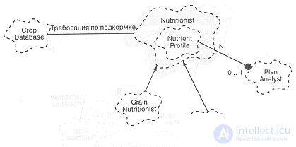
Fig. 5-11. Nesting icon
In accordance with the rules of the chosen implementation language, classes can contain instances of the nested class or use it. Languages usually do not allow inheritance from a nested class.
Typically, class nesting is a tactical decision of the designer, and class nesting is typically a strategic architectural decision. In both cases, the need to use investments to a depth of more than one or two levels is extremely rare.
Export Management. All major object-oriented programming languages allow you to clearly separate the class interface and its implementation. In addition, as described in Chapter 3, most of them allow the developer to define in more detail access to the class interface.
For example, in C ++, class members are open (accessible to all clients), protected (accessible only to subclasses, friends, and the class itself) and closed (accessible only to the class itself and its friends). In addition, some elements may be part of the class implementation and thus be inaccessible even to friends of this class [For example, an object or class described in a .cp file is available only to member functions implemented in the same file]. In Ada, class members can be public or private. In Smalltalk, all instance variables are private by default, and all operations are public. Access is granted by the class itself and only explicitly: the client cannot gain anything by force.
We depict a way to access the following communications decorations:
Мы ставим их как "засечки" на линии связи у источника. Например, на рис. 5-12 показано, что класс GrainCrop множественно наследует от классов Crop (посев) (открытый суперкласс) и FoodItem (пища) (защищенный суперкласс).

Fig. 5-12. Значок управления доступом.
FoodItem в свою очередь содержит от одного до двадцати трех закрытых экземпляров класса VitaminContent (содержание витаминов) и один открытый экземпляр класса CaloricEquivalent (калорийность). Заметим, что CaloricEquivalent мог бы быть записан как атрибут класса FoodItem , так как атрибуты эквивалентны агрегации, мощность которой равна 1:1. Кроме того, мы видим, что класс GrainCrop (посев зерновых) использует класс GrainYieldPredictor (предсказатель урожая зерновых) как часть своей реализации. Это обычно означает, что некоторый метод класса GrainCrop использует услуги, предоставляемые классом GrainYieldPredictor .
Кроме уже рассмотренных в этом примере случаев, обычная ассоциация так же может быть украшена символами доступа. Метасвязь (связь между инстанцированным классом и его метаклассом) не может получить таких украшений.
Символы ограничения доступа можно применять к вложенности во всех ее формах. На обозначении класса мы можем указать доступ к атрибутам, операциям или вложенным классам, добавив символ ограничения доступа в качестве префикса к имени. Например, на рис. 5-12 показано, что класс Crop имеет один открытый атрибут scientificName (ботаническое название), один защищенный - yield (урожай), и один закрытый - nutrientValue (количество удобрения). Такие же обозначения используются для вложенных классов или категорий классов. По умолчанию все вложенные классы и категории являются открытыми, но мы можем указать ограниченный доступ соответствующей меткой.
Types of attitude. In some languages, there are such pervasive types of relationships, with such fundamental semantics, that the introduction of new symbols would be justified. In C ++, for example, there are three such constructs:
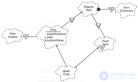
Fig. 5-13. Relationship icons
It is logical to use for them the same decoration in the form of a triangular icon, as for the abstract class, but with the symbols S , V or F, respectively.
Рассмотрим пример на рис. 5-13, который представляет другой ракурс классов, показанных на предыдущем рисунке. Мы видим, что базовый класс OrganicItem (органический компонент) содержит один экземпляр класса ItemDictionary (словарь компонентов) и что этот экземпляр содержится самим классом, а не его экземплярами (то есть он является общим для всех экземпляров). В общем случае мы указываем обозначение static на одном из концов ассоциации или на конце связи агрегации.
Considering the GrainCrop class , we see that the structure of inheritance acquires a rhombic shape (the connections of inheritance, branching out, converge). By default, in C ++, the diamond shape of the inheritance structure leads to the fact that in the leaf classes the structures of the base, twice inherited class are duplicated. In order for the GrainCrop class to receive a single copy of the twice-inherited OrganicItem class structures , we must apply virtual inheritance, as shown in the figure. We can add decoration of virtual communication only to inheritance.
The friend icon can be connected to any type of connection by placing the icon closer to the server, meaning that the server considers the client to be its friend. For example, in fig. 5-13, the PlanAnalyst class is friendly with the Crop class , and therefore has access to its private and protected elements, including both the yield and scientificName attributes .
Physical content. As shown in Chapter 3, an aggregation relationship is a special case of association. Aggregation denotes a whole / part hierarchy and assumes that it is possible to find its parts by an aggregate. The “whole / part” hierarchy does not mean a mandatory physical content: the union has members, but that does not mean that it owns them. On the other hand, a separate record about the sowing physically contains the relevant information, such as the name of the sowing, the harvest and the feeding schedule.
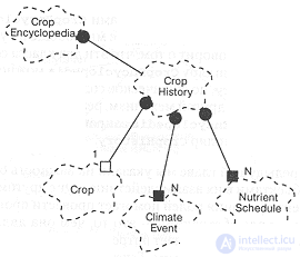
Fig. 5-14. Physical content.
Aggregation is usually detected during analysis and design; clarifying it as a physical content is a detailed, tactical decision. However, it is important to recognize this case, firstly, in order to correctly determine the constructors and destructors of the classes included in the aggregation, and, secondly, to generate and consistently correct the code.
The physical content is marked on the diagram by an ornament at the end of the line denoting aggregation; the absence of this decoration means that the decision on the physical content is not defined. In hybrid languages we distinguish two types of content:
In purely object-oriented languages, especially in Smalltalk, the physical content is only by reference.
To distinguish the physical presence of an object from a link to it, we use a shaded box to indicate aggregation by value and an empty box — to aggregate by reference. As will be discussed later, this style of jewelry is consistent with the corresponding semantics in the object diagrams.
Consider the example shown in fig. 5-14. We see that instances of the class CropHistory (sowing history) physically contain several instances of the classes NutrientSchedule (fertilizer application schedule) and ClimateEvent (climate event). The physical content of aggregation parts by value means that their creation or destruction occurs during the creation or destruction of the aggregate itself. Thus, aggregation by value ensures that the lifetime of the aggregate coincides with the lifetime of its parts. In contrast, each instance of the class CropHistory has only a reference or pointer to one instance of the class Crop . This means that the lifetimes of these two objects are independent, although here too one is the physical part of the other. Another case is the relation of aggregation between the classes CropEncyclopedia (encyclopedia of crops) and CropHistory . In this case, we do not mention the physical content at all. The diagram says that these two classes are in the “whole / part” relation, and that you can find the corresponding instance of CropEncyclopedia in the CropEncyclopedia instance, but the physical content has nothing to do with it. Instead, another mechanism could be developed that implements this association. For example, an object of the CropEncyclopedia class queries the database, and receives a reference to the appropriate instance of CropHistory .
Roles and keys. In the previous chapter, we pointed out the importance of describing the various roles played by objects in their interaction with each other; In the next chapter, we will explore how role identification helps in the analysis process.
In short, the role of abstraction is what it is to the outside world at the moment. Role means a need or ability by which one class is associated with another. Text decoration describing the role of the class is placed next to any association, closer to the class performing the role, as can be seen in Fig. 5-15. In this figure, the classes PlanAnalyst (plan analyzer) and Nutritionist (agrochemist) are both information providers for a CropEncyclopedia class object (they both add information to the encyclopedia), and PlanAnalyst class objects are also users (they view encyclopedia material). In any case, the role of the client determines the individual behavior and the protocol that it uses. Let's also pay attention to the reflective association of the PlanAnalyst class: we see that several instances of this class can cooperate with each other and at the same time they use a special protocol that differs from their behavior in association, for example, with the CropEncyclopedia class.
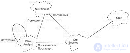
Fig. 5-15. Roles and keys.
This example also shows the association between the CropEncyclopedia and Crop classes, but with a different type of decoration that represents the key (depicted as an identifier in square brackets). A key is an attribute whose value uniquely identifies an object. In this example, the CropEncyclopedia class uses the scientificName attribute as the key to search for the required entry. Generally speaking, the key must be an attribute of the object that is part of the aggregate, and is placed at the far end of the association link. It is possible to use several keys, but the key values must be unique.

Fig. 5-16. Restriction icon.
Limitations. As discussed in Chapter 3, a constraint is an expression of some semantic condition that must be maintained. In other words, a constraint is an invariant of a class or a relationship that must be maintained if the system is in a stable state. We emphasize - in a stable state, because there are possible transitional phenomena in which the state of the system as a whole changes and the system is in an internally mismatched state, so that it is impossible to observe all the imposed restrictions. Compliance with the restrictions is guaranteed only in a stable state of the system.
We use adornments for constraints, similar to those used by us to designate roles and keys: we put the restriction expression enclosed in curly brackets next to the class or connection to which it is attached. The restriction joins individual classes, the association as a whole, or its members.
In fig. 5-16, we see that the EnviromentalController class has a power limit, postulating that there are no more than 7 instances of this class in the system. In the absence of a power limit, a class can have any number of instances. The designation for the abstract class, introduced earlier, is a special case of restriction (zero instances), but since this phenomenon is very often found in class hierarchies, it received its own type of decoration (triangle with letter A).
The Heater class (heater) has a different type of restriction. The figure includes the hysteresis requirement in the heater: it cannot be turned on if less than five minutes have passed since its last shutdown. We apply this restriction to the Heater class, considering that control over its observance is assigned to instances of the class.
Two other types of constraints are depicted in this diagram: restrictions on associations. The association between the EnvironmentalController and Light classes requires that individual light sources be uniquely indexed relative to each other in the context of this association. There is another limitation imposed on the associations of the EnvironmentalController with the classes Heater and Cooler , which is that the controller cannot turn on the heater and the cooler at the same time. This restriction is applied to the association, and not to the Heater and Cooler classes, because its implementation cannot be assigned to the heaters and coolers themselves.
If necessary, you can include in the constraint expression the names of other associations using qualified names used in the project. For example, Cooler :: runs unambiguously names one of the associations of the dispatcher class. In our notation, such expressions are often used in a situation where one class has an association (for example, aggregation) with two (or more) other classes, but at any time each instance can be associated with only one of the objects.
Constraints are also useful for expressing secondary classes, attributes, and associations [In Rumbach’s terminology, this is called derived entities: for them it uses a special icon. Our general approach to constraints is enough to express the semantics of derived classes, attributes, and associations; this approach facilitates the reuse of existing icons and the unambiguous definition of entities from which derivatives are taken]. For example, consider the classes Adult (adults) and Child (children), which are subclasses of the abstract class Person (People). We can provide the Person class with the dateofbirth attribute (date of birth) and add an attribute called age , for example, because age plays a special role in our real-world model. However, age is a secondary attribute: it can be determined via dateofbirth . Thus, in our model, we can have both attributes, but must specify a constraint that determines the output of one of the other. The question of which attributes are derived from which relates to tactics, but the restriction is useful regardless of the decision we made.
Similarly, we could have an association between the Adult and Child classes, which would be called Parent , and could include an association called Caretaker (trustee) if necessary in the model (for example, if formal parenthood relations are modeled in the social system). security). The Caretaker association is secondary: it can be obtained as a result of the Parent association; we can indicate this invariant as a constraint imposed on the Caretaker association.
Associations with attributes and notes. The latter additional concept is related to the task of modeling the properties of associations; In the notation, the problem is solved by introducing an element that can be applied to any diagram.
Consider the example in fig. 5-17. It shows the many-to-many association between the Crop and Nutrient classes. This association means that N (any number) of fertilizers is applied to each crop, and each fertilizer is applied to N (any number) of crops. The NutrientSchedule class is like a property of this many-to-many relationship: each instance corresponds to a pair of sowing and fertilizer. To express this semantic fact, we draw on the diagram a dashed line from the association Crop / Nutrient (association with an attribute) to its property - the class NutrientSchedule (an attribute of the association). Each unique association can have no more than one such attribute and its name must match the name of the attribute class.
The idea of associating associations has a generalization: when analyzing and designing, a lot of temporal assumptions and decisions appear; their meaning and purpose are often lost, because there is no suitable place to store them, and keeping everything in your head is unthinkable. Therefore, it is useful to introduce a designation that allows you to add arbitrary text notes to any element of the diagram. In fig. 5-17, there are two such notes. One of these, attached to the NutrientSchedule class, reports something about the expected uniqueness of its instances (Selects from a common set of schedules); The other (from the fertilizer database) is attached to a specific operation of the Nutrient class and expresses our wishes for its implementation.
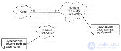
Fig. 5-17. An association with an attribute and a note.
For such notes, we use paper-like icons and connect them to the element to which they relate, with a dotted line. Notes may contain any information: plain text, program snippets, or links to other documentation (all this can be useful when developing design tools). Notes can be unrelated to any element, which means that they belong to the diagram itself [The icon we use is similar to the designation of notes in many windows-systems, especially following the traditions of the Macintosh. The direct instigators of our designation were the sentences Gamma, Help, Johnson and Vlissides [10]].
The specification is a non-graphical form used to fully describe the element of the system of notation: class, association, individual operation, or a whole diagram. Looking through the charts, it is relatively easy to understand the large system; However, a single graphical representation is not enough: we must have some explanations for the figures, and specifications will play this role.
As mentioned earlier, the diagram is a slice of the developed system model. Specifications also serve as non-graphic rationales for each element of the notation. Thus, the set of all syntactic and semantic facts reflected in the diagram should be a subset of the facts described in the model specification and be consistent with them. Obviously, a design tool that supports such a notation can play an important role in maintaining consistency in charts and specifications.
In this section, we first look at the basic elements of the two most important specifications, and then we study their additional properties. We do not set ourselves the task of describing each specification in detail, it depends on the user interface of specific environments that support our notation. We also will not present the specifications of all elements (in particular, metaclass and certain types of links will be out of our attention). In most, such specifications are either a subset of more general specifications, such as class specifications, or do not add anything to the graphical representation. It is especially important to emphasize the following: the specification should reflect what is not expressed in the graphic elements of the diagram; Specifications contain information that is best written in text rather than graphical form.
Common elements. All specifications have at least the following components:
Name: ID
Definition: text
The uniqueness of the name depends on the element being named. For example, class names must be unique in at least the category that contains them, whereas operation names have scope that is local to the class that contains them.
The definition is text that identifies the concept or function presented by the element and is suitable for inclusion in the project’s vocabulary (which is discussed in the next chapter).
Each specification contains minimal information. Of course, the used automated design tool can enter its own columns for the needs of a specific software environment. However, it is important to point out that no matter how many columns the specification includes, you should not fool the developer into stupid rules by which he must fill in all parts of the specification before proceeding to the next stage of development. Designations should facilitate development, and not create additional difficulties.
Class specifications Each class in the model has exactly one specification, which contains at least the following items:
Responsibilities: text
Attributes: Attribute List
Operations: list of operations
Restrictions: list of restrictions
As stated in the previous chapter, class duties are a list of guarantees of behavior provided to them. The next chapter will show how we use this column to record the responsibilities of the classes that we discover or invent during the development process.
The remaining items — attributes, operations, restrictions — correspond to their graphic counterparts. Some operations may be so important that they should be supplied with their own specifications, which we will discuss below.
These basic concepts can be represented in terms of the chosen implementation language. In particular, all this information, as a rule, is unambiguously recorded by a class declaration in C ++ or by the package specification in Ada.
As mentioned in Chapter 3, often the behavior of some important classes is best expressed in the finite state machine language, therefore we will include an additional column in the class specification:
Automatic: link to automatic
The use of additional elements of the notation requires the following items to be entered into the class specification:
Export Management: open | implementation
Power: Expression
The meaning of these points is completely identical to their graphic counterparts. Parameterized and instantiated classes should include the following clause:
Parameters: a list of formal or actual parameters
The following optional items do not have graphic equivalents; they serve to indicate some functional aspects of a class:
Resilience: instant | constant
Parallelism: sequential | guarded | synchronous | active
Memory Location: Expression
The first of these properties reflects the lifespan of objects of a class: a permanent entity is one whose state can survive the object itself, as opposed to instantaneous, whose state disappears with the expiration of the object's lifetime.
The second property shows the extent to which a class can work in a multi-threaded system (see Chapter 2). By default, objects are sequential, that is, they are designed for one stream. Guarded and synchronous classes "stand" several threads. At the same time, the protected class expects that the client flows somehow agree on mutual exclusion so that only one of them works with it at a time. The synchronous class itself provides mutual exclusion of clients. Finally, the active class has its own thread.
The last item contains information about absolute or relative memory consumption by objects of this class. We can use this column to calculate the size of a class or its instances.
Operations specifications For all operations-
Класс возвращаемого значения: ссылка на класс
Аргументы: список формальных аргументов
Эти графы можно заполнить на выбранном языке реализации. В соответствии с правилами языка можно включить еще один пункт:
Квалификация: текст
В C++, например, этот пункт может содержать утверждение о том, является ли операция статической, виртуальной, чисто виртуальной или константой.
Использование дополнительных элементов обозначений требует введения дополнительной графы:
Доступ: открытый | защищенный | закрытый | реализация
Содержание этой графы зависит от языка реализации. Например в Object Pascal все атрибуты и операции всегда открытые, в Ada операции могут быть открытыми или закрытыми, а в C++ возможны любые из четырех указанных случаев.
Использование дополнительных элементов обозначений требует также введения графы
Протокол: текст
Эта графа происходит из практики языка Smalltalk: протокол операции не имеет семантического значения, а служит просто для именования логической совокупности операций, вроде таких, как initialize-release (инициализация-освобождение) или model access (доступ к модели).
Следующие необязательные графы не имеют графических аналогов и служат для формального описания семантики операции:
Предусловия: текст | ссылка на текст программы | ссылка на диаграмму объектов
Семантика: текст | ссылка на текст программы | ссылка на диаграмму объектов
Постусловия: текст | ссылка на текст программы | ссылка на диаграмму объектов
Исключения: список исключительных ситуаций
Первые три пункта могут быть заполнены в любой из перечисленных форм. Последний содержит список исключительных ситуаций, содержащий имена соответствующих классов.
Последняя серия необязательных граф служит для описания некоторых функциональных аспектов операции:
Параллельность: последовательный | охраняемый | синхронный
Память: выражение
Время: выражение
Первые две аналогичны одноименным графам в спецификации класса. Третья - относительные или абсолютные оценки времени выполнения операции.

Comments
To leave a comment
Object oriented programming
Terms: Object oriented programming