Lecture
So, let's talk about the requirements. What we are, in general, we understand - when a customer describes to us exactly what he wants, we always hear phrases like "I would like the update check to be carried out automatically, as in antiviruses," "I want a big green button in the center of the window which starts the process "," the program should allow viewing and printing reports "," and so that everything is pretty, with translucencies, as in Vista "," confirmation should be displayed when exiting ", etc., etc. Of course as true developers, we understand that the customer never knows that he needs it, but if he understands, he cannot explain. But the phrases are always, in fact, the same! They describe how the customer imagines the system, what the customer wants from the system, the functionality that he expects from it, the requirements that it imposes on it.
If we turn to the classics, for example, to the same "gang of three" (Jacobson, Butch, Rambo), we learn that the requirement is the desired functionality, property or behavior of the system . It is with the collection of requirements that the software development process begins. If you portray the software development process as a black box (sure, the reader knows what it is, if not - Wikipedia is at your service), at the output of which we get a software product, then the input of this black box will be it is a set of requirements for a software product (Fig. 6.1)!

By the way, which diagram resembles this drawing? Correctly, the activity diagram. And the choice of this particular diagram is absolutely justified here - remember, we said that activity diagrams are often used to describe business processes? The only caveat: usually the development process does not end with the release of a software product - a new iteration is coming, new, refined requirements, a new version, etc.
By the way, back to the requirements. Yes, we said that a set of requirements is being sent to the input of our “black box”. But in what form? How do they document these requirements? I think most readers remember that such a technical task is the main document, without which no project was started in Soviet times. The document was a large, multi-page, with a clear structure defined by the state standards (state industry standards). And he described, in fact, nothing more than the requirements for the system being created!
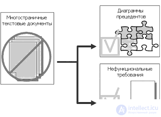
The technical task is a good thing in its own way. But as time went on, standards changed, notations, ways of describing requirements. And gradually, the technical assignment gave way to a set of artifacts consisting of two types of documents:
Use case diagrams constitute a use case model (use cases, use-cases). A precedent is a system functionality that allows the user to get some meaningful, tangible and measurable result. Each use case corresponds to a separate service provided by the simulated system in response to a user request, that is, it determines how to use this system. It is for this reason that use cases, or precedents, often appear in Russian terminology as use cases . Use cases are most often used to specify external requirements for the system being designed or to specify the functional behavior of an existing system. In addition, use cases implicitly describe typical ways of user interaction with the system, allowing to work correctly with the services provided by the system.
Non-functional requirements are the description of such system properties as environmental and implementation features, performance, extensibility, reliability, etc. Non-functional requirements are often not tied to a specific use case and therefore put on a separate list of additional system requirements (Fig. 6.2).
But back to the precedents (use cases). Identify the use cases and actors - the duty of a system analyst. And he does this in order to:
This type of activity is usually performed in the following sequence:
At first, the requirements are drawn up in the form of a plain text document, which is created either by the user himself, or by the user and the developer together. Further requirements are made in the form of a table. The precedents are placed in the left column, and the actors involved in the precedent are placed in the right column.
Consider an example. The secretary places on the server a lunch menu for the week. Employees should be able to familiarize themselves with the menu and make an order by choosing dishes for each day of the next week. The office manager must be able to generate an invoice and pay it. The system must be written in ASP.NET. Such a simple Internet application for automating lunch orders to the office.
We think everything is clear here. A table describing the requirements may be, for example:
| Precedent | Actor |
|---|---|
| place menu | secretary |
| read the menu | employee, secretary, office manager |
| make an order | employee, secretary, office manager |
| form an account | Office Manager |
| pay the bill | Office Manager |
Here it is not said anywhere that the system should be written in ASP.NET. Why - it is clear: this is not a functional requirement! And yet, it is obvious that the secretary and the office manager are also employees. A reader who has carefully read previous lectures will suspect that in this case, by creating a model of precedents, speaking of the actors, a generalization could be applied. Indeed, a use case diagram based on this table may be, for example, such (Fig. 6.3):
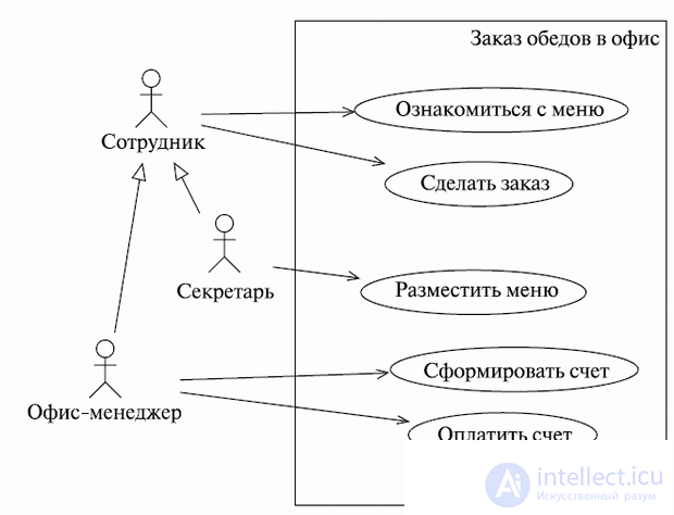
Well, we have an example of a chart. So, what elements do we see on it? The first thing that catches your eye is a large rectangle, inside which ellipses are placed, denoting, as we already understood, precedents. At the top of the rectangle, the name of the system being modeled is indicated, and is called its system boundary (system boundary, subject boundary), context or simply system . This element of the diagram shows the boundary between what you, as an analyst, have shown in the form of precedents (within this framework), and what you have depicted as actors (outside of them). Most often, such a rectangle shows the boundaries of the simulated system itself . That is, there are precedents inside the border - the functionality that the system implements (and in this sense, precedents can be viewed as representations of the subsystems and classes of the model), and outside - actors : users and other external entities that interact with the simulated system.
It should be said that the framework of the system is depicted in case diagrams quite rarely, since they are implicitly implied by the diagram itself. In fact, this element does not add any additional significant information to the diagram, so its use is a matter of taste for the analyst. The appearance of the system framework in the use case diagram is most often dictated by the characteristics of the personal design style.
In addition to the framework of the system or its context in the diagram, we see two more types of entities related to it - actors (actors, actors) and precedents . Let's start with ektorov. Quite often in the Russian literature on UML to refer to the characters can be found the term "actor". In principle, its meaning is more or less clear and the original English term is consonant. Moreover, there is another reason for such a transfer. What is the first word that comes to your mind when you hear the word "actor"? Yes, of course - the word "role"! It is about the roles that we will soon talk about when we try to figure out what lies behind the notion of the “actor”. In the meantime, may the reader forgive us, then we will still use the word "Ector" - a transcription of the original term. I remember that we already wrote about our attitude towards the literal translation of terminology ...
So, what is the meaning of the concept of ector? Ector is a set of roles that the user performs in the course of interaction with a certain entity (system, subsystem, class). An ector can be a person, another system, a subsystem, or a class that represents something outside the entity under consideration. Ectors "communicate" with the system through the exchange of messages. By clearly distinguishing ectors, you thereby clearly define the boundary between what is inside the system and what is outside is the framework of the system.
Perhaps the words "roles played by the user" in the definition of ector do not sound very clear. Very funny this concept is explained in Zicom Mentor:
a role is not a specific user, but a kind of hat that a person puts on when interacting with an entity.
Indeed, put on a pirate's hat - and you are Captain Jack Sparrow, and put on a top hat and you - Jack the Ripper! Joke ... "Physical" user can play the role of one or even several ektor, performing their functions in the course of interaction with the system. Conversely, the role of the same ector can be performed by several users.
On the UML diagrams, ectors are depicted as stylized men, because, as you remember, of course, the idea was to create a notation, any symbol of which can easily be drawn by hand (Fig. 6.4):
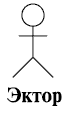
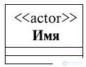
Despite the “human” type of this designation, one should not forget that actors are not necessarily people. An actor, as we said earlier, can be an external system, a subsystem, a class, etc. By the way, the little man ("stick-person") is not the only ector designation used in UML. On the use case diagrams, the “human-like” form of ector is usually used, but on other diagrams, and especially in cases where ector has attributes that are important to show, the image of ector is used as a class with the << actor >> stereotype (Fig. 6.5):
With the system, ectors, as we have said, communicate through messages, but if we talk at a higher level of abstraction, in terms of the model of precedents, they interact with the system through precedents. The same ector can be associated with several precedents, and vice versa, one precedent can be associated with several different ectors. Associations between the actor and the precedent are always binary — that is, they represent one-to-one relationships, the use of multiplicity is unacceptable. This does not contradict the above: indeed, one ector can be associated with several precedents, but only with the help of separate associations — one for each precedent. We saw it in our example. By the way, there we saw associations depicted not just as lines, but with arrows. We think the meaning of this notation is quite clear: this directional association and the arrow (as on other diagrams) are always directed towards the entity from which they demand something, whose service they use, etc.
And yet - ectors cannot be connected with each other. The only permissible relationship between ectors is generalization ( inheritance ). Again, in our example of ordering meals to the office, you could see exactly this kind of relationship between the ectors. This does not mean that in real life the office manager and secretary (and indeed any two employees) cannot communicate: it is simply that when creating a model of precedents such communication does not fall within our area of interest, it is considered irrelevant.
Another type of elements found in case diagrams, moreover, which gave them a name, is the actual use cases , or use cases. A precedent is a description of a set of consecutive events (including possible variants) performed by the system that lead to the result observed by the ector. Precedents describe the services provided by the system to the ectors with which it interacts. Moreover, the precedent never explains how the service works, but only describes what is being done.
The precedents are depicted in the form of an ellipse, inside the outline of which the name (description) of the precedent is placed. The use case name is usually much longer than the names of other model elements. Why this is so, in principle, is understandable: the name of a precedent describes the interaction of the ector with the system, which indicates how they exchange messages with each other. In our example of ordering meals, we saw several precedents and surely the reader noticed that the name of the precedent is rather the name of the script reproduced during the interaction of the ector with the system. Moreover, this is always a description from the ector's point of view , a description of the services provided by the system to the user. Let us give an example of the simplest diagram illustrating what we said about the precedent designations (Fig. 6.6).
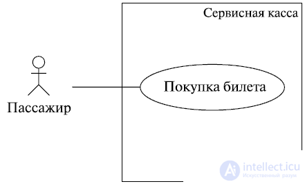
In this example, a passenger can buy a ticket for a certain type of transport at the service desk. Ticket purchase is the name of the scenario for which the ector (passenger) can interact with the system (cash desk). Notice that this is not a description of the scenario, but the name - it tells us what the ector does in the process of interaction, but does not say how! And yet - the precedents define disjoint behavior scenarios. The execution of one precedent cannot be interrupted as a result of the work of another precedent. In other words, the execution of one use case cannot be interrupted as a result of events or actions caused by the execution of another use case. Precedents act as atomic transactions whose execution cannot be interrupted.
The attentive reader may have noticed how imperceptibly we introduced the word " script ". What is a script and how does the notion of a scenario relate to the notion of a precedent? The first question is well answered by the classics (G. Butch):
A script is a specific sequence of actions that illustrates behavior.
A scenario is a narrative story about actions performed by an actor, a story, an episode occurring in a given time frame and a given context of interaction. Scenarios (in various forms of presentation) are widely used in software development. As we have just noted, script writing resembles the writing of an artistic story, and this explains the fact that the use of scripts is widespread among analysts, who often have artistic or literary abilities. Despite the continuous narrative nature, scenarios can be viewed as a sequence of actions (to make a storyboard ). When developing a user interface, scripts describe the interaction between a user (or a category of users, for example, system administrators, end users) and the system. Such a scenario consists of a sequential description of combinations of individual actions and tasks (for example, keystrokes, clicks on control elements, data entry into the appropriate fields, etc.). Recall, for example, descriptions of sequences of user actions (intended to achieve certain results, solving certain tasks) that you find in the help to a little-known program. The same can be said about fashion now "how-to videos", in which such sequences are displayed visually, with specific examples. In any case, the purpose of such reference materials is to provide a description of typical system use scenarios, interaction scenarios between the user and the system.
Scripts can also sometimes be seen in a use case diagram. Sometimes they are depicted in the form of a " sheet of paper " on which the file name is written - a rectangle with a curved lower left corner. In this case, the specified file contains the description of this script. And sometimes the script is written in a comment. As you probably remember, comments (notes, notes) are depicted as rectangles with a curved upper right corner and are connected to the element that they explain with a dotted line (Fig. 6.7).

As we already mentioned, scripts can be written in various forms. It can be a structured, but non-formalized text, a formalized structured text, pseudo-code, a table, a diagram of activities, finally! Each script describes, in a narrative form, a complete, concrete interaction that has a definite goal from the user's point of view. Если рассматривать табличную форму представления сценария, то линия, разделяющая левый и правый столбцы таблицы, символизируют собой границу, отделяющую действия пользователя от ответных действий системы. Табличная форма особо подчеркивает участие пользователя, что является очень важным аспектом при разработке пользовательского интерфейса.
Вот пример простого (неформализованного) текстового описания сценария.
Пользователь вводит логин, пароль, адрес электронной почты и код подтверждения и нажимает кнопку "Далее". Система запрашивает ввод проверочного кода. Пользователь вводит код и нажимает кнопку "Далее". Система проверяет соответствие кода изображенному на картинке .
Не правда ли, знакомая процедура? Да, это описание регистрации пользователя на некотором сайте. Правда, не совсем полное: не рассмотрены случаи, когда выбранный пользователем логин уже занят, адрес электронной почты введен неправильно, пароль не удовлетворяет требованиям или код не соответствует изображенному на картинке. О таких случаях - альтернативных сценариях - мы поговорим чуть позже.
А вот тот же сценарий в табличном представлении:
| Действия пользователя | Реакция системы |
|---|---|
| Ввод логина, пароля, адреса электронной почты и нажатие кнопки "Далее" | Запрос ввода проверочного кода |
| Ввод проверочного кода и нажатие кнопки "Далее" | Проверка кода на соответствие изображенному на картинке |
Вы, конечно, заметили, что этот сценарий можно детализировать - например, прежде чем попросить ввести проверочный код, система отображает картинку, на которой этот самый код изображен. Т. е. запрос на ввод кода включает в себя вывод картинки с упомянутым кодом. Об этом мы тоже еще поговорим.
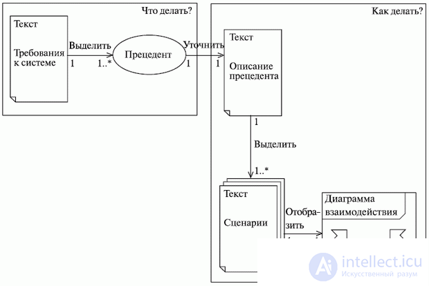
А пока попробуем ответить на второй вопрос, а именно: как связаны понятия сценария и прецедента . Прецеденты, как мы уже говорили, рождаются из требований к системе. Но говорят они о том, что делает система. Как система это делает, говорят сценарии. Таким образом,прецедент можно специфицировать путем описания потока действий или событий в текстовой форме - в виде, понятном для "постороннего" (не занятого в непосредственной разработке системы) читателя. А ведь такое описание - это и есть сценарий! Таким образом, сценарии специфицируют прецеденты . And further. Поскольку сценарии - это, по сути, рассказы, они являются весьма эффективным средством извлечения информации из бесед с заказчиком и предоставляют превосходное, понятное непрофессионалу описание создаваемого приложения. Сценарии, да и вообще диаграммы прецедентов (дополненные сценариями) являются отличным средством общения между разработчиками и заказчиком , причем, в силу простоты нотации, - средством, понятным обеим сторонам. В конечном итоге, взаимосвязь между требованиями, прецедентами и сценариями можно изобразить такой "псевдодиаграммой" (рис. 6.8).
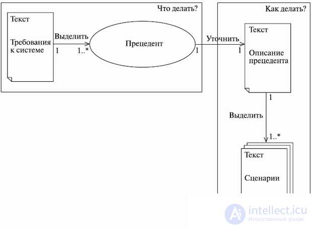
Как видите, для каждой ассоциации на диаграмме проставлена кратность и ее смысл вполне понятен, но все же о кратности следует поговорить отдельно. Один прецедент определяет несколько сценариев, каждый из которых представляет один из возможных вариантов определяемого прецедентом потока событий. Сценарии так же соотносятся с прецедентами, как экземпляры класса, т.е. сценарий - это экземпляр прецедента , как объект - экземпляр класса. Система может содержать, например, несколько десятков прецедентов, каждый из которых, в свою очередь, может разворачиваться в десятки сценариев. Как правило, прецедент описывает не одну последовательность действий, а множество, и выразить все детали рассматриваемого прецедента с помощью одной последовательности действий обычно не получается. Практически для любого прецедента можно выделить основной сценарий, описывающий "нормальную" последовательность действия, и вспомогательные , описывающие альтернативные последовательности, которые инициируются в случае возникновения определенных условий.
Другой вопрос: требуется ли такое уточнение модели прецедентов, оправдано ли оно для данного уровня приближения, или "подразумевающиеся" альтернативные сценарии можно опустить? Например, в предыдущем примере с покупкой билета в сервисной кассе мы не изобразили сценарии (и, соответственно, прецеденты), соответствующие вариантам, когда билетов на выбранный пассажиром рейс уже не осталось, пассажир изменил свое решение и хочет взять билет на другой рейс, когда оплата идет наличными или по кредитной карте и т. д.
"Хватит ходить вокруг да около!" - воскликнет нетерпеливый читатель. Уже заканчиваем. Мы просто хотели мягко подвести читателя к вопросу об отношениях между прецедентами. А отношения эти весьма многообразны. Начнем со старого знакомого - отношения обобщения (наследования, генерализации). О генерализации мы уже говорили не раз, когда рассматривали диаграммы классов. Но все же напомним суть этого понятия. Как говорят классики, обобщение - это отношение специализации (обобщения), в котором объекты специализированного элемента (потомка) могут быть подставлены вместо объектов обобщенного элемента (родителя, или предка).
Точно так же, как мы обычно поступаем с классами, после того как мы выделили и описали каждый прецедент, мы должны просмотреть их все на предмет наличия одинаковых действий - поискать, а не выполняются ли (используются) некоторые действия совместно несколькими вариантами использования. Этот совместно используемый фрагмент лучше описать в отдельном прецеденте. Таким образом мы уменьшимизбыточность модели за счет применения обобщения прецедентов (иногда, правда, говорят не об обобщении, а об использовании прецедентов; почему - сейчас поймете). Как это и "положено" при наследовании, экземпляры обобщенных прецедентов (потомков) сохраняют поведение, присущее обобщающему прецеденту (предку). Другими словами, наличие (использование) в варианте использованияX обобщенного варианта использования Y говорит нам о том, что экземпляр прецедента X включает в себя поведение прецедента Y. Обобщения применяются, чтобы упростить понимание модели вариантов использования за счет многократного задействования "заготовок" прецедентов для создания прецедентов, необходимых заказчику (помните, как мы рассматривали вопрос о том, всегда ли необходимо создавать новый класс, или лучше воспользоваться готовым решением, чувствуете аналогию?). Такие "полные" прецеденты называются конкретными прецедентами . "Заготовки" прецедентов, созданные лишь для многократного использования в других прецедентах, называют абстрактными прецедентами. Абстрактный прецедент (как и абстрактный класс) не существует сам по себе, но экземпляр конкретного прецедента демонстрирует поведение, описываемое абстрактными прецедентами, которые он (повторно) использует. Прецедент, который экторы наблюдают при взаимодействии с системой ("полный" прецедент, как мы называли его ранее), часто называют еще " реальным " прецедентом.
Как мы уже говорили выше, обобщение (наследование) чаще всего используют между классами и интерфейсами. Однако другие элементы модели также могут находиться между собой в отношении наследования - например, пакеты (о которых мы тут не говорим), экторы, прецеденты...
A generalization is depicted, as an attentive reader, of course, remembers, with a line with an "uncolored" triangular arrow at the end. A generalization is the relationship between an ancestor and descendant, and the arrow always points to the ancestor. If we recall that descendants inherit (use) the properties of the ancestor, it is quite logical to recall our assertion that the arrows in the UML are always directed towards the one from whom they demand something, whose services they use (Fig. 6.9):
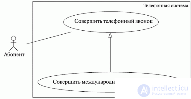
It can be used to create different types of patterns. Descendants ect. This is the way to the child.
The next type of relationship between precedents is inclusion. The inclusion relationship means that at some point in the base case, the behavior of another case is contained . The included precedent does not exist by itself, but is only a part of the ambient precedent. Thus, the basic precedent, as it were, borrows the behavior of those included, decomposing into simpler precedents. For example, when we buy a thing in a store, when a cashier reads a bar code, the state of the database of goods available is updated - the number of cash units of the purchased goods decreases. The same action is carried out in the event that the purchased goods turned out to be defective, unusable, or simply did not like us: the state of the said database is updated again - but now towards the increase in the number of cash units of a certain product. That is, both of these actions, both purchase and return, contain (include) such an action as updating the database contents.
But what about inclusion? It’s very simple - as a dependency (dotted line with an arrow, remember?) With the stereotype << include >>. In this case, the arrow is directed, naturally, towards the precedent to be included. This fact is easy to explain, if we recall the statement that we have already used several times in this course: the arrow is always directed in the direction of the element from which something is required, whose services are used. And if we assume that the ambient precedent includes borrowing (using) the behavior of the included precedents, it becomes clear that the arrow can only be directed in this way. And here is a diagram illustrating the above, which we borrowed from Zicom Mentor (Fig. 6.10):
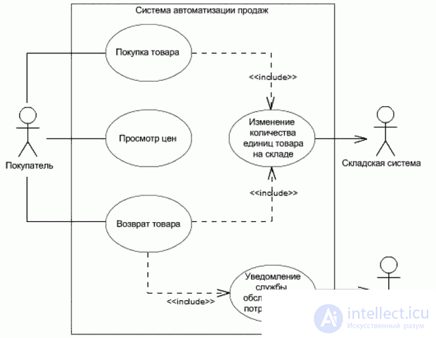
As is well seen from this example, the use of inclusion allows you to avoid multiple descriptions of the same set of actions - the general behavior can be simply described as a precedent included in the baseline.
The next step is the expansion ratio. In order to understand the meaning of the expansion, let us imagine that we are talking about paying for some goods purchased by us. We can pay for goods in cash if the amount does not exceed $ 100. Or pay by credit card if the amount is in the range of $ 100 to $ 1000. If the amount exceeds $ 1000, we will have to take out a loan. In this way, we have expanded our understanding of the operation of paying for goods purchased and in cases when using other means of payment than cash. But these cases themselves occur only under strictly defined conditions: when the price of the goods falls within a certain framework.
The extension complements the use case with other use cases that “work” under certain conditions — it simply adds to the source precedent a sequence of actions contained in another use case. The relation of the extension of precedent A to precedent B means that an instance of precedent B may include (under certain conditions that can be described in the extension; how exactly described, we will say a little later) the behavior described in precedent A. The example is shown in the following diagram (fig. 6.11):
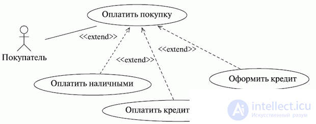
However, in the above example, it is not visible under what conditions the person uses each particular method of payment. At the same time, when modeling with the use of an extension, it is possible to indicate both the conditions for the implementation of the extended behavior and the place — the point of expansion of the precedent, in which actions from the expanding precedents are connected. Remember the unconditional jump operator, which you hopefully didn’t use in your programs too often. As soon as the interpreter reaches this operator, it transfers control to the string that is marked with the label specified in this operator. However, in the case of an extension, we are talking more about a conditional transition operator - when the initial precedent (namely, the sequence of actions contained in it) comes to the extension point, the expansion conditions are evaluated. If the conditions are met, the precedent includes a sequence of actions from the expanding precedent.
The extension point is described in the additional section of the case, separated from its name by a horizontal line - just as in separate sections the attributes of the class and its operations are listed. Below is an example of the description of the extension point, which we borrowed from Zicom Mentor (Fig. 6.12).

In this example, the check-in of passengers of the flight includes the control of the security service, and under the condition (indicated in the note after the service word "Condition:") that the person often flies and the cabin is full (pay attention to the AND operator, speaking about the simultaneous fulfillment of conditions), ticket class can be upgraded, for example, from economy to business class. Moreover, such an upgrade can occur only after a ticket is submitted to the registration desk - this is the expansion point. She is described (her name is indicated) in the additional section of the precedent after the service phrase "Extension points:". Anticipating the reader’s question, we say that a precedent can have arbitrarily many points of expansion. You can compare a specific expanding precedent with a specific extension point by reading the extension conditions specified in the comments - the condition itself is written after the service word "Condition:" in curly brackets, followed by the service phrase "Extension point:", and after it is indicated extension points. Look again at our example with the registration of passengers at the airport and see for yourself that all this is very simple!
Some confusion may be caused by the fact that the arrow is always directed towards the expanding precedent. But this is easy to explain from the point of view of our thesis that “the arrow always points to the one that is demanded of”, because in order for the precedent to be extended, it is necessary that it gets to the extension point and verify the truth of the conditions - only then the actions contained in the expanding case can be added to the sequence of actions of the source case. So everything is correct - the point of extension and the verification of conditions are required of the expanding precedent, and therefore the arrow is pointing towards it.
Summarizing all the above, we can say that the expansion allows modeling the optional behavior of the system (was the ticket class better if the passenger had not flown the required number of miles and the salon was almost empty?). The fact of expansion depends on the fulfillment of the conditions - expansion may not happen! These are just separate sequences of actions that are performed only under certain circumstances and are included at certain points in the scenario (usually as a result of an explicit interaction with the actor).
The organization of precedents through the allocation of general behavior (inclusion) and various behaviors (expansion) is an important part of the process of developing a simple, balanced and understandable set of precedents. It can even be said that the use of inclusion and extension is a sign of good style in the modeling of precedents.
At this point, the conversation about the notation of precedent diagrams could be completed. I would just like to say a few words about the relationship between the concepts of precedent and cooperation . We already talked about cooperation earlier (remember the interaction diagrams?) As a set of roles working together to provide some system behavior. We also mentioned that the precedents answer the question “what does the system do?”, But they don’t say how it does it. At the stage of analysis, it is not really necessary to understand exactly how the system implements its behavior. But in the transition to implementation, it would be nice to know which particular classes (or other elements of the model), working together, provide the desired behavior . That is, we logically moved from talking about precedents to talking about cooperation! It is not for nothing that the notations of cooperation and precedent are very similar (the reader, of course, remembers that cooperation is indicated by a dotted ellipse) (Fig. 6.13).

So what is the relationship between precedent and cooperation? It follows logically from the previous paragraph that this is an implementation relationship. Each precedent is implemented by one or more cooperatives. This, of course, does not mean that classes are strictly distributed to cooperatives: classes that participate in cooperatives that implement a certain precedent will participate in other cooperatives.
The use case model is essentially a conceptual model of the system. In it, as we have repeatedly noted, only the behavior (functionality) of the system is described in general terms, and the details of the implementation are not discussed - at this stage the implementation is not important, it is much more important to gather the requirements for the system and arrange them in a visual form, understandable both to developers, and to the customer.
So, summing up, we can formulate three reasons for the use of precedents. Or rather, there are three ways to use precedents (it’s not by chance that in Russian translation you can often find the phrase “use case”!) When working on the system:
Precedents are useful for both direct and reverse engineering. With direct design, we, in fact, carry out the "translation" of the UML into a certain programming language. And test the created application should be based on the event streams described by precedents. Reverse engineering involves translation from a programming language to a language of UML diagrams. These things have to do for a number of reasons:
a great idea after the first translation from UML to a programming language is to do a reverse translation and compare the original and restored UML models (it is desirable that these translations are performed by different teams). This will make sure that the design of the system corresponds to the model, no information was lost during the translation, and simply to catch some "bugs". This approach is called reverse semantic tracing (or RST - Reverse Semantic Traceability) and is developed by INTSPEI (http://www.intspei.com) as one of the basic techniques of the INTSPEI methodology P-Modeling Framework, brief information about which you can find in the application to this course.
And finally, it should be noted that, of course, only precedent diagrams, like the scenarios they define, are not enough to create a model of system behavior. As we have already mentioned many times, precedents say what the system does, but they don’t say how. This is indicated by scripts, but in text form, which makes them rather difficult to read. Interaction diagrams that visualize scripts come to the rescue. Thus, we can now supplement our old "pseudo-diagram" and calm down on this (Fig. 6.14):
In conclusion, we give a couple of examples of completed use case diagrams. The first example (the meaning of which is clear and without additional explanations) demonstrates the inclusion, expansion and inheritance of precedents. Pay attention to the arrows that are directed to the ector, depicting the gateways. That's right - because the system uses their services when sending messages, while the marketer, on the contrary, uses the services of the system, and therefore the arrows are directed from it (Fig. 6.15).

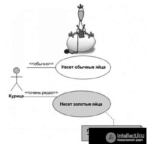
The following three examples, by tradition, we borrowed from the joke site on UML (http://www.umljokes.com), continuing to argue that you can joke on UML — it is a full-fledged language of communication that can be applied just like any other. The first of these examples is a part of the well-known fairy tale about "The Hen Ryaba", which the author has very colorfully designed (Fig. 6.16).
The second diagram, also well-formed, tells us that ducks do not like to pay for beer, preferring to drink on credit (Fig. 6.17).
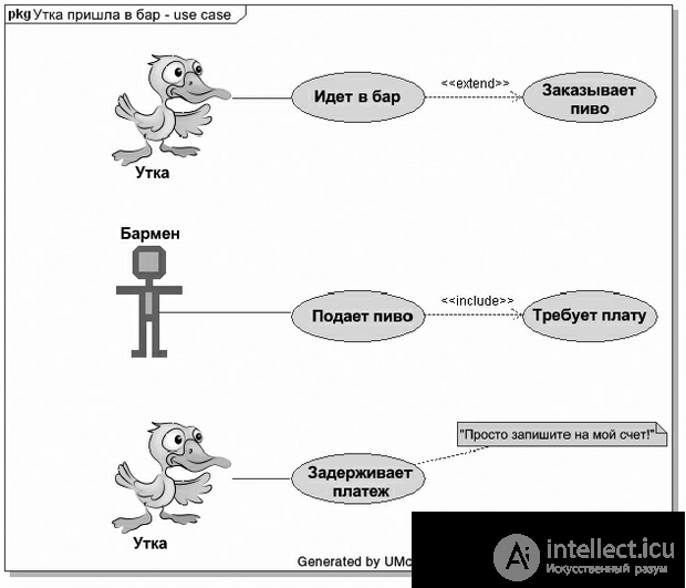
By the way, pay attention to the frame of the diagram shown in this example - a rectangle separating the content area of the diagram and having in the upper part a special section for its name.
And finally, the third picture, which is not a good example of a precedent chart, but just fun. This is a story about methods of behavior that allow guaranteed (!) To fail any exam (Fig. 6.18):


Comments
To leave a comment
Web site or software design
Terms: Web site or software design