Lecture
DFD is a common abbreviation for English. Data Flow Diagrams - data flow diagrams. This is the name of the methodology of graphical structural analysis, which describes the sources and data recipients external to the system, logical functions, data streams and data stores accessed.
The data flow diagram (DFD) is one of the main tools for structural analysis and design of information systems that existed before the wide distribution of UML. Despite the current shift in emphasis from the structural to the object-oriented approach to the analysis and design of systems, the “old” structural notation is still widely and effectively used both in business analysis and in the analysis of information systems.
The standard for describing business processes DFD - Data Flow Diagram is translated as a data flow diagram and is used to describe top-level processes and to describe actual data flows in an organization.
| Main elements | Features | Uses, Pros and Cons | |
| Dfd | Job, Streams, External entities Storage. | Does not set the sequence of work. Displays how a business process converts informational and material flows. | Building a network of business processes; Charting data flow diagrams |
The created models of data flows of the organization can be used in solving such tasks as:
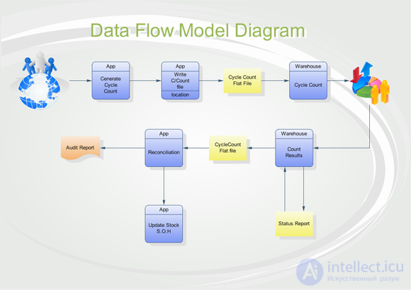
Data flow diagrams show how each process converts its input data to output, and identifies the relationship between these processes. DFD presents the simulated system as a network of related work.
When building a DFD business process diagram, one should remember that this scheme shows material and information flow and in no case speaks of a temporal sequence of work , although in most cases the temporal sequence of work coincides with the direction of flow in the business process.
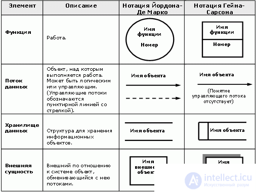
There are two DFD notation:
Job title = Action + Object, on which the action is performed
[note] For example, if this work is related to the action of selling products, then it should be called <Product sales> [/ note]1. The name of the stream must be formulated according to the following formula:
Thread Name = Object representing the stream + Object Status
[note] If we are talking about products that have been shipped to a customer, then the stream can be called <Products shipped> or <Products shipped to a customer>. In this case, <Products> is the object that represents the stream, and <shipped to the customer> is the status of the object. [/ Note]
2. The name should be as short as possible and consist of 2-3 words.
The construction of the DFD model is based on the principle of decomposition. DFD-model includes three documents that refer to each other: Graphic diagrams, Mini-specification, Data Dictionary.
The first step is to build a contextual diagram. The diagram has a star topology, in the center of which is the so-called main process, connected with receivers and sources of information, through which users and other external systems interact with the system.

However, in some cases it is more expedient and clearer to build several context diagrams with a hierarchy:
In this context, the top level diagram contains not the only main process, but a set of subsystems connected by data streams. Context diagrams of the next level detail the context and structure of the subsystems.
After constructing the context diagrams, the resulting model should be checked for completeness of the initial data about the system objects and the isolation of the objects (lack of information links with other objects).
For each subsystem that is present in context diagrams, its refinement is performed using the DFD diagram. Each process, in turn, can be detailed using a separate diagram or a mini-specification.
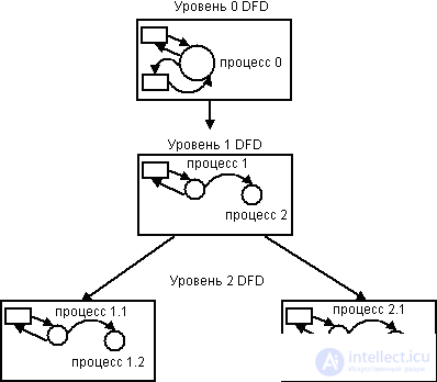
When detailing the following rules should be followed:
[note] For example, processes detailing process number 12 receive the numbers 12.1, 12.2, 12.3, etc. [/ note]
Mini-specification is a document that describes in detail the logic of the process. It contains the process number, lists of input and output data, the process body - a detailed function algorithm that converts input data streams to output.
The minispecification is the final vertex of the DFD model hierarchy. The decision to complete the process specification and the use of a mini-specification is made by the analyst based on the following criteria:
The data dictionary defines the structure and content of all data streams and data collectors that are present in the diagrams.
For each stream, the dictionary stores: stream name, type, attributes.
| Type of | Attributes |
|
|
After building a complete system model, it must be checked for completeness and consistency.
A model is considered complete if all its objects (subsystems, processes, data streams) are described and detailed in detail.
A model is considered consistent if all the data streams and data collectors comply with the information retention rule : all incoming data should be read, and all read data should be recorded.

Comments
To leave a comment
Web site or software design
Terms: Web site or software design