Lecture
The class symbol in a chart may look differently depending on the chart’s details:
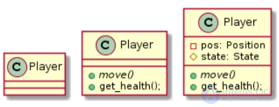
Issues of detail will be discussed in the following sections, and now we need to note that the class symbol contains the name (Player), the set of operations (move, get_gealth) and attributes (pos, state). For class elements, the type, multiplicity, visibility, etc can be specified:
Attribute specification format:
visibility name: type [multiplicity] = default_value
Operation specification format:
visibility name (argument: type) = return_type
Depending on the visibility parameter, the element may be:
The virtual function and the name of the abstract class are in italics, and the static function is underlined.
Types of patterns
 - behavioral (behavioral);
 - generators (creational);
 - structural (structural).
Symbols of relations between classes
 - aggregation - describes the relationship "part" - "whole", in which the "part" can exist separately from the "whole". The diamond is indicated by the "whole".
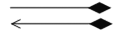 - composition (composition) - a subspecies of aggregation in which "parts" cannot exist separately from the "whole".
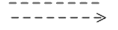 - dependence (dependency) - a change in one entity (independent) may affect the state or behavior of another entity (dependent). From the direction of the arrow indicates an independent entity.
 - generalization (generalization) - the ratio of inheritance or implementation of the interface. From the direction of the arrow is a superclass or interface.
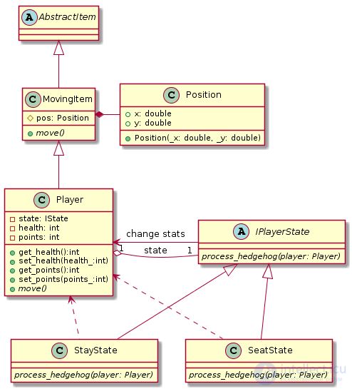
The game has different types of elements (walls, chests, characters). All these elements are descendants of the AbstractItem abstract class, with some of them able to move (such elements must be inherited from MovingItem). Inheritance (the “is” relationship) is depicted using a solid line with a closed arrow pointing towards the superclass - in the diagram, the MovingItem class inherits from AbstractItem, the Player class from MovingItem, etc. The dashed line with the closed arrow sets the relation of realization (closed inheritance).
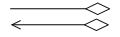
Another type of relationship between classes is inclusion; in object-oriented programming, there are two types of this relationship — composition and aggregation. Recall that composition is a kind of inclusion, when objects are inextricably linked to each other (their lifetime coincides), in the case of aggregation, the lifetime is different (for example, when an object of a nested class can be replaced by another object during program execution).
The composition relation is indicated by a filled in rhombus, which is drawn from the side of the enclosing class — for example, the MovingItem class includes the Position class, since a moving object always has a position. The aggregation relation is represented by an empty diamond - the player (Player) aggregates the state (IPlayerState).
If you are familiar with the State, Strategy or Delegation patterns, you can skip the section.
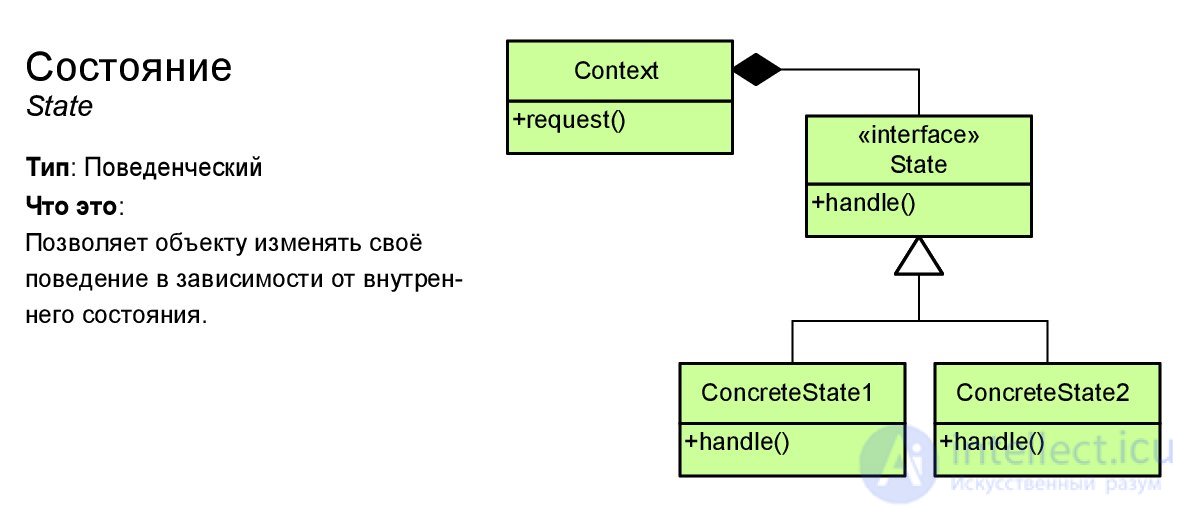
The diagram above uses the State design pattern (a State), which is a type of Delegation pattern and is close to the Strategy pattern. The essence of delegation lies in the fact that in order to simplify the logic of the class, a part of its work can be transferred (delegated) to the auxiliary class. In turn, the State pattern can be added, for example, at the stage of refactoring, if in several class functions there is a razlapistya check of the state of an object to perform certain actions. In our case, the character can interact with the hedgehog, suppose that if the character moves sitting and contacts the hedgehog, his health should decrease, and if he stands, the score (points) will increase. In addition to the hedgehog, there could be food, opponents, ammunition, etc. To demonstrate this pattern, the abstract class IPlayerState and two heirs StayState and SeatState are created. In the Player class, when you press the Ctrl button, the state could change to SeatState, and when released, to StayState. Thus, when executing state-> process_hedgehog ( this ), our player in some way, defined by the state object, contacts the hedgehog.
The Delegation design pattern (and all its variants) is a good example for demonstrating aggregation. In our case, the player’s state may change due to the change of the object according to the pointer, i.e. the lifetime of objects varies.
The most common type of relationship between classes is an association, indicated by a solid line (sometimes with an arrow). In general, both composition, and aggregation, and generalization (inheritance) are special cases of association. In our diagram, using association, it is shown that the IPlayerState class changes the stats (health and points) of the Player object. The association may have a name of the relationship explaining the essence of the relationship. The name of the corresponding variable is often used as the name of the relations of composition and aggregation. In addition, the association can have multiplicity, it is set at the ends of the line:
The last kind of relationship, which we consider - dependence, is represented by a dashed (dashed) line. If there is an arrow, then it is directed from the dependent to the independent class, if the arrow is not present, then the classes depend on each other. Dependence is an interface dependence, i.e. if the interface of an independent class changes, then you have to make changes to the dependent class. In our diagram, SeatState and StayState depend on the Player class, since refer to his methods for changing player characteristics. To depict the friendship between classes, the dependency relationship with the signature friend is used .
Obviously, not all types of relationships should be displayed on the diagram and one relationship can be replaced by another. So, I would remove the dependency relationship from our example, but under certain circumstances (for example, when sketching on a whiteboard) they would be quite appropriate. The arrangement of multiplicities and names of links is also not performed in all cases. In general, do not put extra information on the chart. The main thing is that the diagram should be visual.

Keeper (memento)

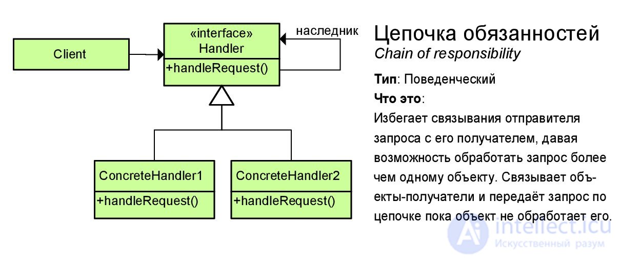
Chain of responsibility
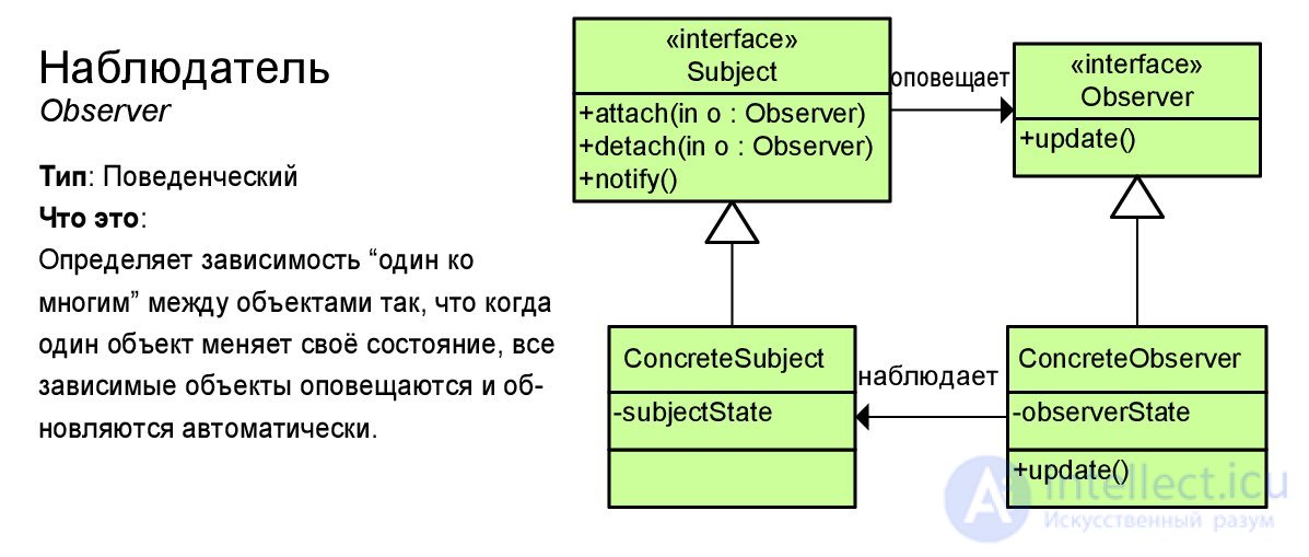
Observer
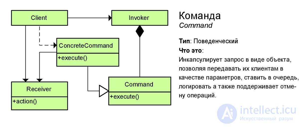
Command (command)
State
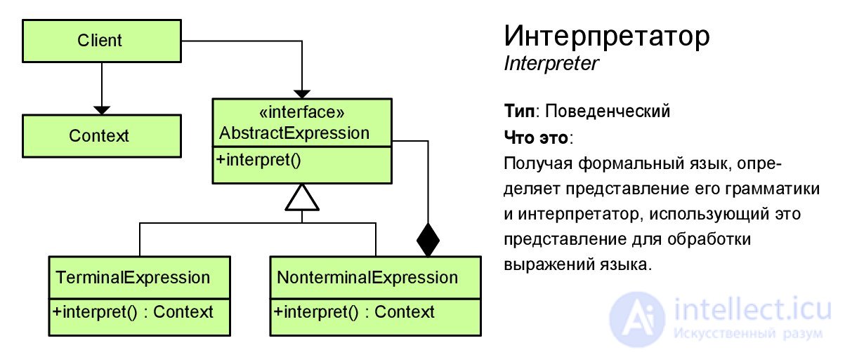
Interpreter
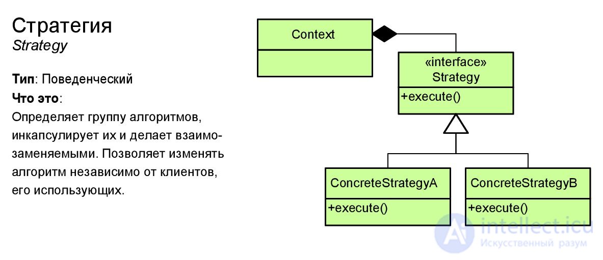
Strategy
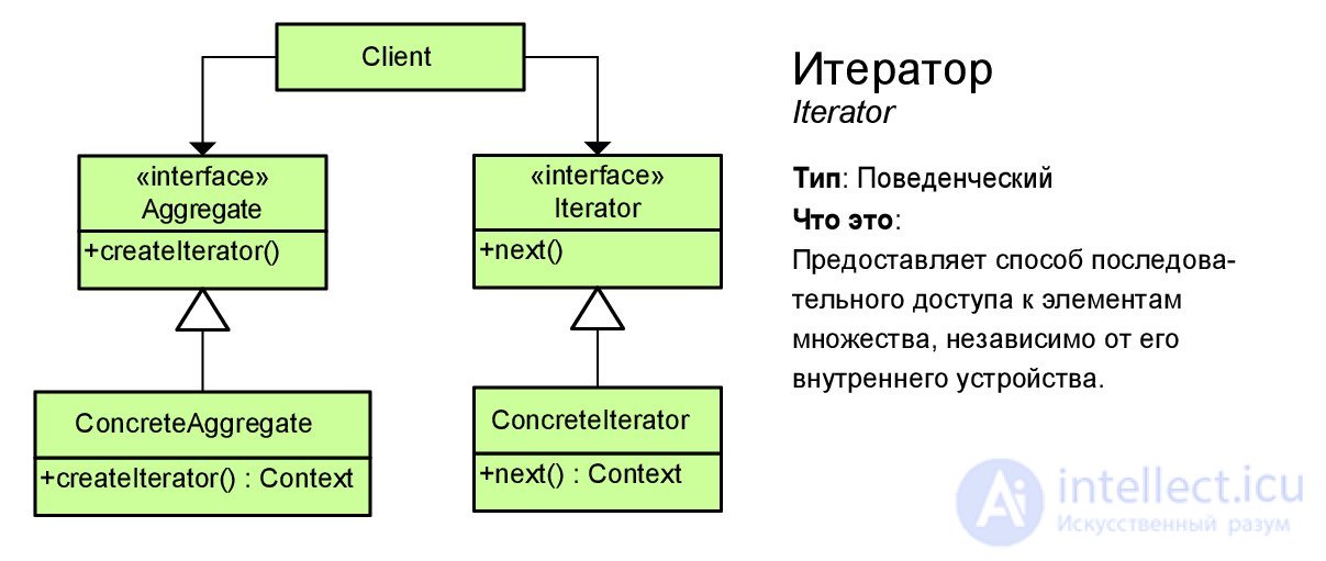
Iterator
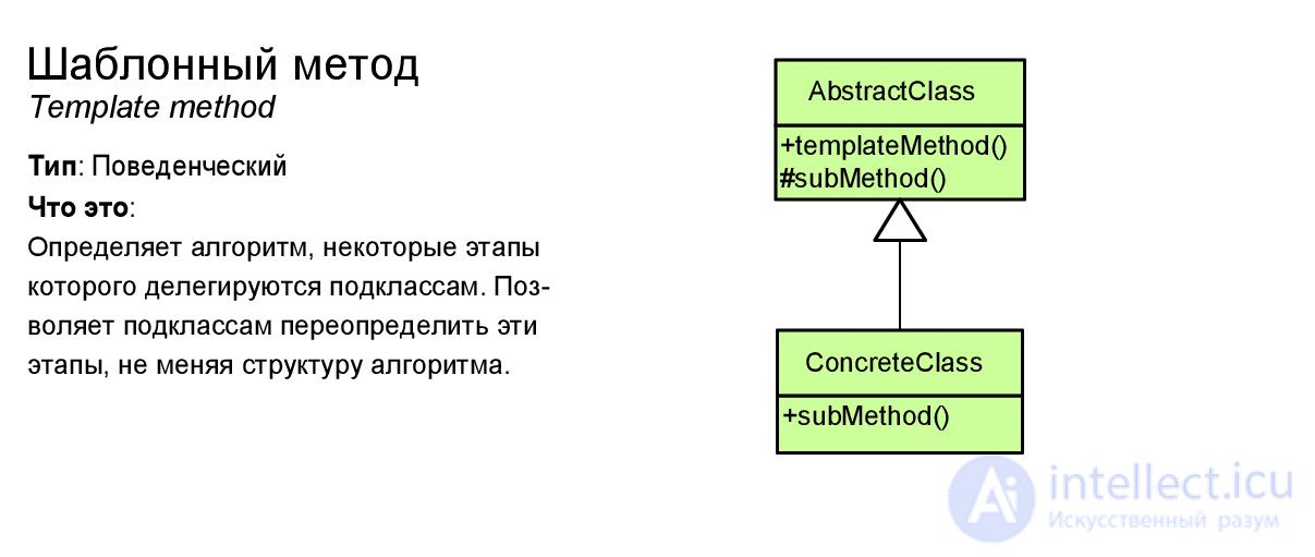
Template Method
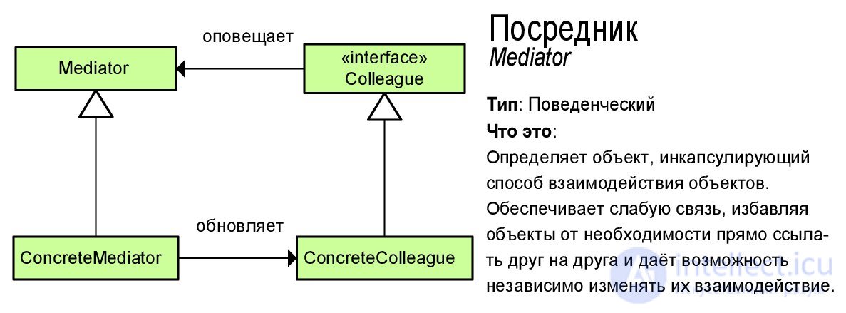
Mediator
Visitor

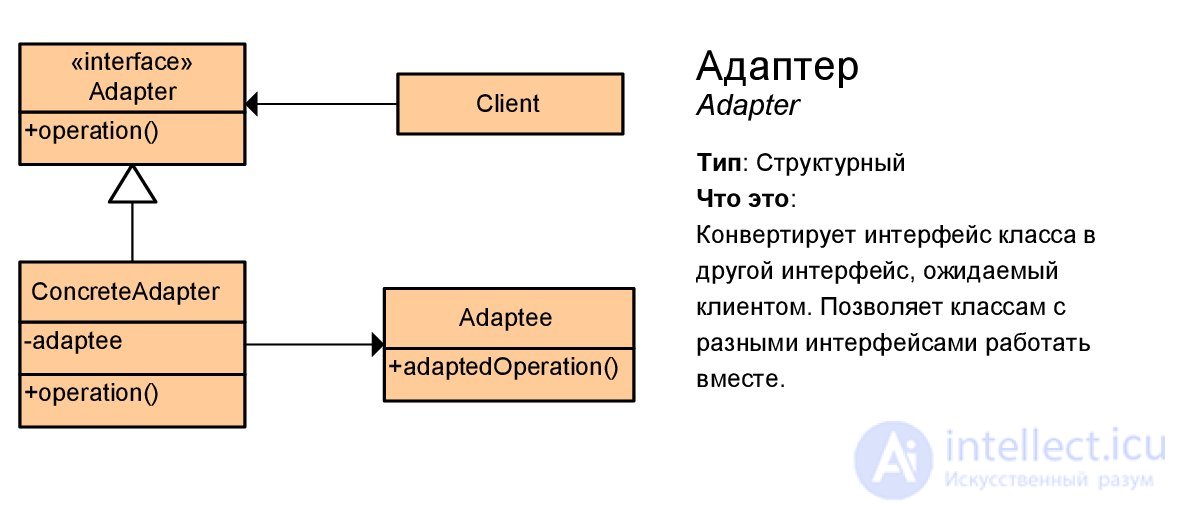
Adapter
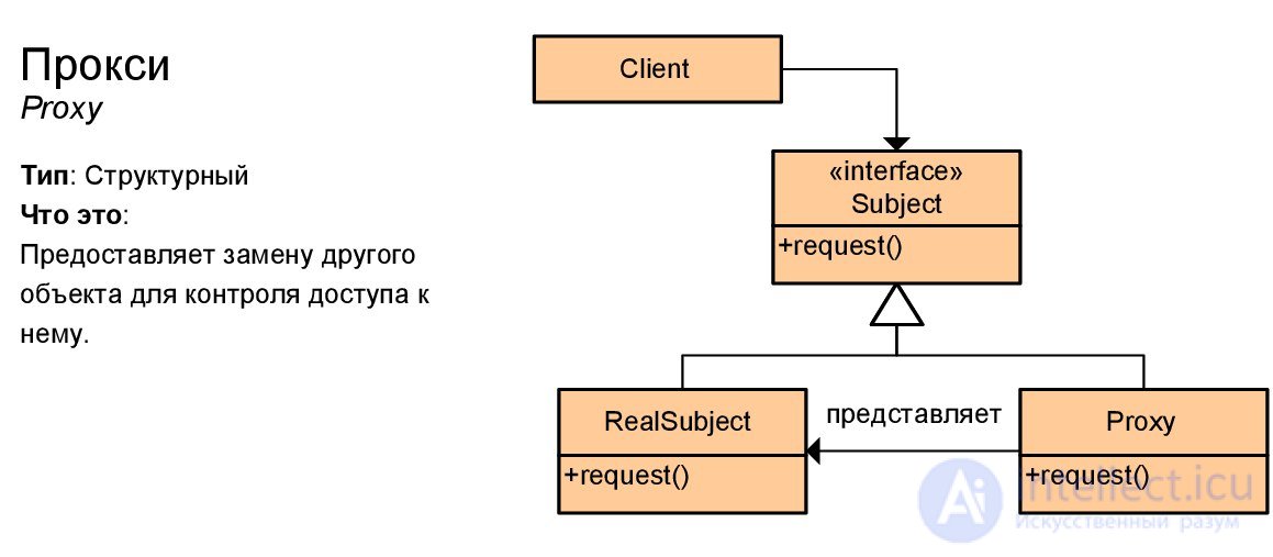
Proxy (proxy)
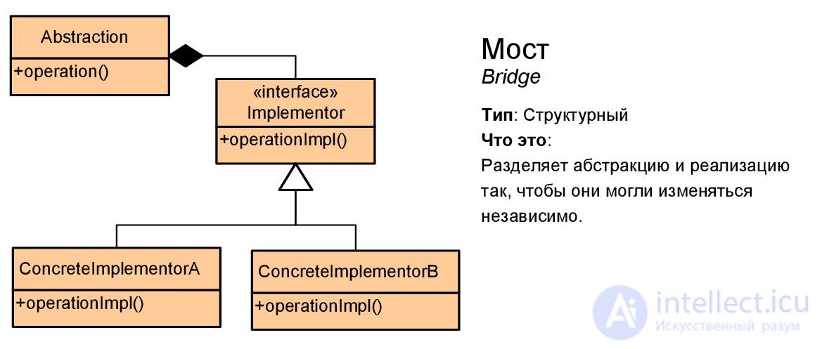
Bridge
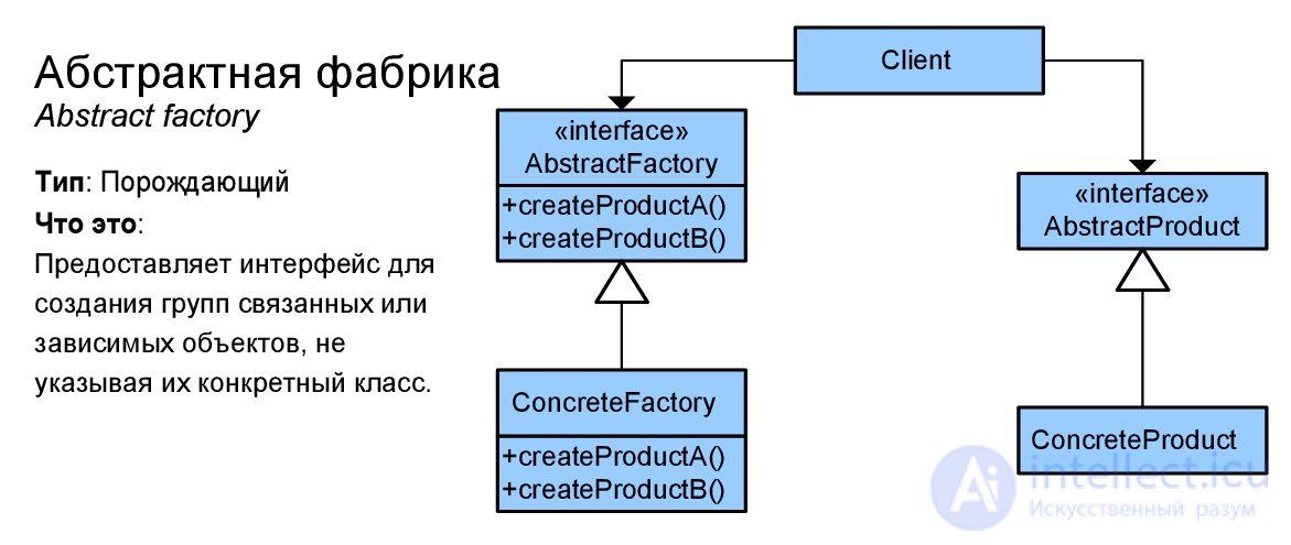
Abstract factory
Linker (composite)

Builder

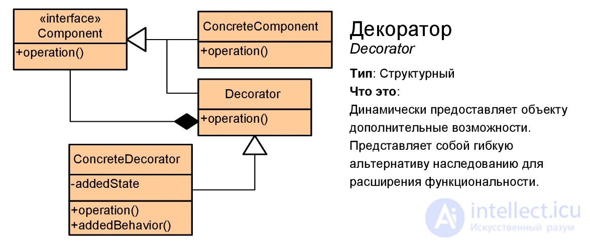
Decorator
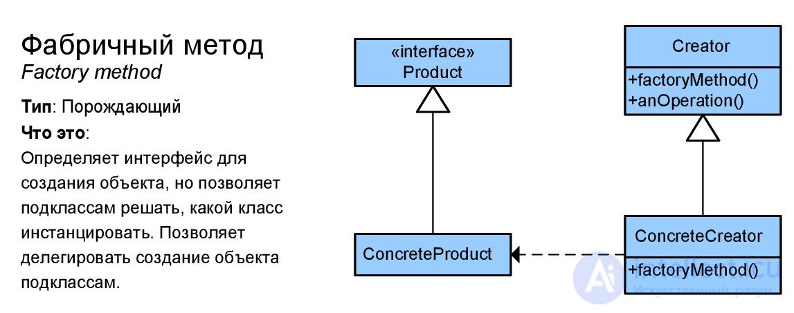
Factory method
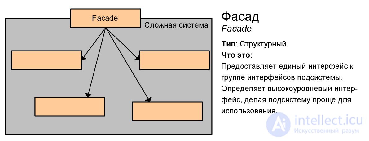
Facade
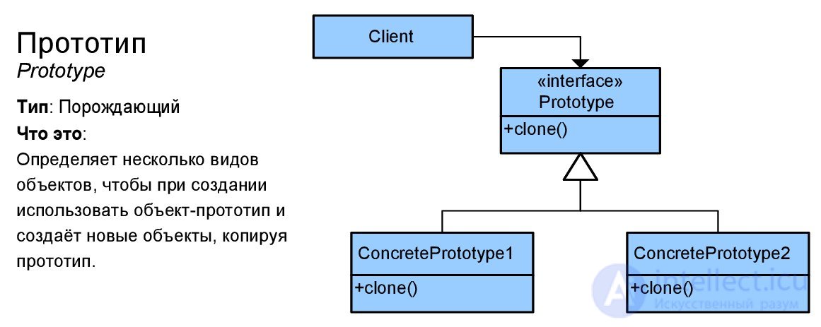
Prototype
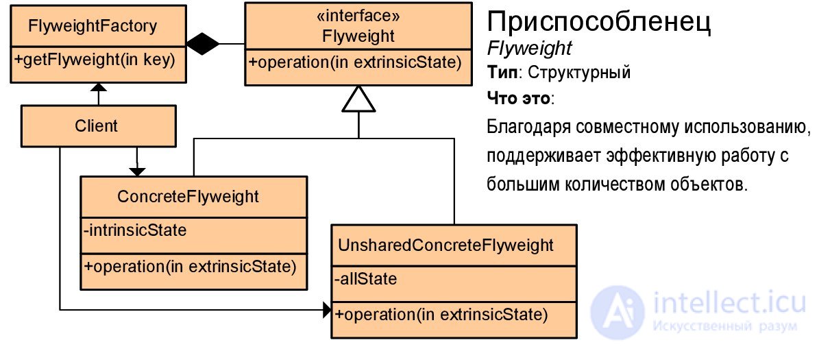
Flyweight
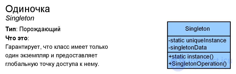
Singleton
We considered the basic notation used in class diagrams - they should be sufficient in most cases. At least, owning this material you can easily understand the diagrams of design patterns and understand the sketch of any project. However, how to build such diagrams correctly? In what order and with what degree of detail? - The answer depends on the purpose of the chart, so the material will be divided into subsections in accordance with the objectives of the simulation.
It is worth noting that Gradi Buch has tips on using UML in the book “User Guide” [Buch_Rambo], but in his “Object Oriented Analysis” [Buch] you can find good examples and project quality criteria. Leonenkov [Leonenkov] avoids this topic altogether, leaving only references to literature, I found specific recommendations from Larman [Larman] and Rosenberg [Rosenberg], part of the material is based on my personal experience. Fowler views UML as a means of sketching, so he has his own (very different from Butch and Rosenberg) view of the [Fauler] class diagram.
The system dictionary is formed in parallel with the development of a use case diagram, i.e. technical specifications. It looks like this - you ask the customer questions like “what else can the user do?”, “What will happen (should the system issue) if the user does click on button?”, And write down the answers to them in the form of a description of precedents. However, the customer, giving answers, can call the same things with different names - from personal experience: by saying “cell”, “intersection”, “node” and “cell”, the customer can mean the same thing. In your system, all these concepts should be represented by one abstraction (class / function / ...). To do this, when communicating with the customer, it is worthwhile to fix the terminology in the form of a system dictionary - the class diagram copes with this very well.
Grady Buch to build a dictionary of the system offers to perform in the following order [BuchRambo]:
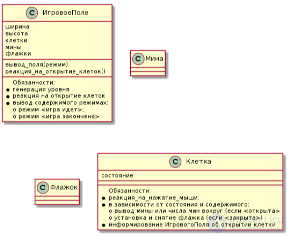
As an example, consider the dictionary system for the game "Minesweeper". The diagram below shows the variation that resulted from my student’s discussion of the problem. It can be seen that the diagram shows the entities and their attributes that are understandable for the customer; this diagram should be seen before drawing up precedents so as not to call the “Cell” - “Field”, misleading everyone. When constructing a system vocabulary, you should avoid drawing class functions on a diagram, since this detailed assignment of responsibilities is best performed after the construction of interaction diagrams.
In the design process, the vocabulary of the system can be supplemented, Rosenberg demonstrates this very well in his book describing the iterative ICONIX design process [Rosenberg]. For example, after reviewing several cases, it may turn out that several classes implement the same functionality — to solve a problem, it is necessary to spell out the responsibilities of each class more clearly, perhaps add a new class and transfer some of these responsibilities to it.
Larman proposes to build a conceptual model of the system [Larman] - this is approximately what we described as a system dictionary, but in addition to the terms of the subject area, it records some relationships that are understandable to the customer. For example, the customer understands (and fixes in the technical task) that is made up by - therefore, there is a relationship between the seller and purchase "makes out". I recommend building a conceptual model, modifying the system’s vocabulary, although Larman recommends adding associations first, and then adding attributes.
In any object-oriented design process, the class diagram is the result, because is the model closest to the implementation (code). There are tools that can convert a class diagram into code — this process is called code generation and is supported by many IDE and design tools. For example, Visual Paradigm performs code generation (available as plugins for many IDEs), new versions of Microsoft Visual Studio, UML modeling tools such as StarUML, ArgoUML, etc. To build good code using a diagram, it must be sufficiently detailed. It is about such a chart in this section.
Before Larman [Larman], before the construction of a design level class diagram begins, interaction diagrams and a conceptual model of the system should be constructed. The order of construction of the diagram is as follows:
Отношения, добавляемые на диаграмму классов уровня проектирования отличаются от тех, что были в концептуальной модели тем, что они могут быть не очевидны для заказчика (эту диаграмму он вообще смотреть не должен — она разрабатывается для программистов). Если на этапе анализа технического задания мы могли выделить основные сущности, не задумываясь о том, как это будет реализовано, то теперь обязанности между нашими классами должны быть окончательно распределены.
Например, при анализе задания на игру «Сапер» мы выделили классы <Флажок> и <Мина>, но будут ли эти классы в окончательном проекте или останутся только в воображении? — решение можно принять только проанализировав диаграммы взаимодействия. Ведь возможен и такой код:
Поясню (для тех, кто не пишет на С++) — тут создается перечисление, которое задает тип ячейки. Ячейка может принимать одно из этих шести значений (пустая открытая, пустая закрытая, пустая закрытая с флажком и т.п.). В таком случае, ячейка никак не сможет сама реагировать на нажатия мыши и отвечать за свое отображение (например пустая открытаядолжна выводить число мин вокруг себя) — все эти обязанности, видимо, лягут на класс PlayingGround.
Пример выше утрированный и однозначно не является образцом хорошего проектирования — на класс PlayingGround возложено слишком много обязанностей, но могли ли мы учесть это при анализе технического задания? Сможем ли мы это сделать до разработки диаграмм взаимодействия для проекта любой сложности? — именно поэтому построение диаграммы классов является последним этапом проектирования.
Под эскизированием понимают моделирование некоторой (интересной нам в данный момент) части системы. Например, эскизирование может выполняться на маркерной доске когда в вашу компанию попадет новый сотрудник и вы будете помогать ему «влиться» в существующий проект. Очевидно, что если если дать человеку диаграмму классов уровня проектирования — разбираться он будет долго. Суть эскизирования в избирательности — вы выносите на диаграмму только те элементы, которые важны для пояснения того или иного механизма.
Сторонником применения UML для эскизирования является Фаулер [Fauler], который считает, что целостный процесс проектирования с использованием UML слишком сложен. Эскизирование применяется очень часто (не только при объяснении проекта на маркерной доске):
Каких-либо конкретных рекомендаций к эскизам диаграмм классов предложить невозможно, кроме того, обычно это достаточно простая задача. Важно понимать суть — избирательность представления элементов снижает сложность восприятия диаграммы.
Частным случаем диаграммы классов является диаграмма «сущность-связь» (ER диаграмма), используемая для моделирования логической схемы базы данных. В отличии от классических ER диаграмм, диаграмма классов позволяет моделировать поведение (триггеры и хранимые процедуры).
Обычно ситуация выглядит следующим образом — вы разработали систему, состояние которой нужно сохранять между запусками, например:
Хранимые между запусками данные должны каким-то образом загружаться по запросу пользователя, т.е. должны задаваться параметры соответствующих классов. Например, приложение должно получить из базы данных список треков (маршрутов) и отобразить его в виде списка в меню программы. При выборе элемента списка — запросить в БД параметры трека, создать объект трека и отобразить его на карте. В любом случае, данные с базы используются при инициализации объектов программы — это важно понимать.
Для моделирования схемы БД с помощью диаграммы классов нужно [Buch_Rambo]:

Comments
To leave a comment
Web site or software design
Terms: Web site or software design