Lecture
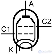
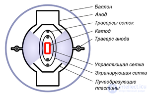
A radiation tetrode is a four-electrode shielded lamp in which a high-density space charge is created to suppress the dinatron effect. Due to the special design of the grids and special ray-forming electrodes, the electron current in the radiation tetrode is focused into narrow beams (rays). A high spatial charge density creates a potential barrier near the anode of the lamp, preventing the outflow of secondary electrons from the anode to the screening grid.
The radial tetrode was invented in the early 1930s as a functional replacement of pentodes in the output stages of audio frequency amplifiers (ULF). The absolute majority of ray tetrodes are designed to work in the output cascades of the ASF and video amplifiers. Circuit design and properties of such cascades are almost identical to the amplifier stages on the pentodes. Amplifiers on ray tetrodes have better efficiency than pentodes, but are more affected by magnetic fields. The output beam tetrode is a practically essential component of a tube guitar amplifier. In modern UZCH high fidelity, ray tetrodes and pentodes are relatively rare due to the fact that they are inferior to direct-field triodes in the level and spectral composition of the distortions.

The classic vacuum triode has a fundamental, unrecoverable drawback - high throughput capacity, limiting the range of amplified frequencies. To amplify the frequencies of the shortwave range, the throughput capacity should have been drastically reduced. In 1926, Albert Hull solved the problem by placing an additional screening grid between the control grid and the anode of the triode. Henry Round (Eng.) Russian, who worked at Marconi (Eng.) Russian., First brought the idea of Hull to mass production, and in 1927 radio frequency tetrodes with a passable capacity of no more than 0.025 pF entered the market [1] .
Another fatal disadvantage of the triode was the low efficiency of the triode audio frequency amplifiers. The tetrode, which is naturally non-linear due to the unavoidable dinatron effect, was of little use for this task. In the same 1926, the problem of efficiency was solved by a group of Gilles Holst (nid.) Russian. from the Physical Laboratory Philips (nid.) Russian. [2] [3] . Bernard Tellegen placed between the screening grid and the anode of the tetrode a third grid electrically connected to the cathode. This grid was relatively rare and had almost no effect on the primary flow of electrons from the cathode to the anode, but effectively blocked the current of the secondary electrons from the anode to the shielding grid. The round came to the same idea in the same year of 1926, but the leadership in the invention of pentodua already belonged to Tellegen, and the patent to Philips [2] . Bell Labs [4] , Marconi-Osram, RCA and the Japanese KO Vacuum Tube [5] radio factories purchased a license for the production of pentodes from Philips, and EMI did not want to pay royalties for the Tellegen patent and began searching for its own solution [6] [7] .
In 1931 [8], the engineers of EMI Cabot Seaton Bull and Sidney Rodd (Eng. Cabot Seaton Bull, Sidney Rodda ) proposed a tetrode construction in which physical barriers were placed between the cathode-grid node and the radiating electrodes that were insulated from the anode, either dielectric barriers (for example, ceramic bearing crossbars), or dielectric coating applied directly to the inner surface of the anode. One half of the anode of the Bulla and Rodda lamp collected the cathode current, the other was “in the shadow” of the barrier. According to Bull and Rodda, such a barrier contributed to the creation in the anode region of a space charge that suppresses the dinatron effect [9] . The cathode-grid Bulla and Rodda lamp unit repeated the construction of an ordinary tetrode with indirect heating.
In 1934-1935, British radio engineer John Henby Owen Harris (eng. John Henby Owen Harries ) invented the so-called Harris lamp (eng. Harries valve ) - a tetrode with an "abnormally large" distance between the shield grid and the anode (eng. Abnormal spacing between the anode and outer grid [10] ). The cathode-grid node of Harris's lamp differed from ordinary tetrodes in that the winding step of the second (shielding) grid coincided with the winding step of the first (control) grid — so that the turns of the second grid were “in the shadow” of the turns of the first grid. The principal difference between the Harris lamp and its modern tetrodes and pentodes was the relatively large size of the cylindrical anode, which filled the entire volume of the lamp. The distance between the second grid and the anode was several times greater than the distance between the second grid and the cathode. Harris found that if a certain critical distance between the second grid and the anode is exceeded, the tetrode changes its properties: the unwanted dinatron effect disappears, the current-voltage characteristic takes the form of an almost perfect broken line with a sharp fracture at the border of the interception and return zones [11] . Harris argued that the IVC fracture in his lamps occurred at lower anode voltages than the pentodes that existed at that time, so the power amplifier on the Harris lamp had more efficiency than the pentode amplifier [10] . The Harris Lamp was commercially produced by the British High Vacuum Valve Company (abbr. HIVAC) [10] .
In 1935–37, the American RCA and the British Marconi-Osram combined the ideas of Harris, Bull and Rodda and released high-grade ray tetrodes to the US and UK markets. In the UK, the production program was based on KT66 medium-power lamps [12] (KT from English kinkless tetrode , “tetrode without kinking [VAC]” - a synonym for “ray tetrode”). The British tried to produce small-beam ray tetrodes (KTW63, KTZ63), but this direction was not successful due to the higher cost than the pentodes [12] . In the United States, the beam tetrode line was extended from below with a lower power lamp 6V6, and from above with a high power lamp 807 [12] . At the end of the 1930s, the production of American beam tetrodes was started in the USSR (6P3S, 6P6S - analogs of 6L6 and 6V6 in glass cylinders). In continental Europe dominated by Philips and Telefunken - here the radiation tetrode was not needed. Beam tetrodes exceeded the pentodes of the 1930s in efficiency and voltage gain [13] , but not enough to conquer the European market. Thus, the development of powerful lamps was divided into two branches — the beam tetrode in the USA and the UK, and the pentode in continental Europe [12] .
During the Second World War, the German radio industry was crushed, and British factories ceased production of “sound” radiation tetrodes [14] . It was resumed only in 1947 [14] , but in 1949–1950 Mullard (a Philips subsidiary) launched a powerful EL34 new generation pentode, a functional replacement for KT series lamps, and a few years later - an EL84 pentode, a 6V6 functional replacement. Typical EL34 and EL84 incorporation schemes developed by Mullard reflected the current consensus of European radio engineers [15] . A few years later, a similar process took place in the USSR - the “outdated” 6P6S lamps were replaced by the newest 6P14P, the EL84 analogue. Despite the success of EL34 (which the USSR was never able to repeat [16] ), the British continued to improve radial tetrodes. In the mid-1950s, the latest generation of “sound” ray tetrodes entered the market — the super-power KT88 and the optimized sublineral mode KT77 [17] . At the same time, a number of specialized lamps were released, optimized for operation in line-wise amplifiers of television sets (EL36 and its Soviet analogue 6P31S, EL500 and its analogue 6P36S, etc.) and flash lamps for computing technology (6P34S).
The similarity of the electrical properties and circuit design of ray tetrodes and powerful pentodes has led to the confusion of these terms in the literature. In reference books and classifiers, these lamps are combined in one section, for example, “Output pentodes and ray tetrodes” [18] . In different reference books, the same lamp can be called both the beam tetrode and the pentode - despite the fundamental differences in the internal structure of these types of lamps. So, in the reference book of Katsnelson and Larionov in 1968, the 6P1P radiation tetrode is called a pentode , despite the fact that the attached figure shows radiation-forming plates unusual for pentode [19] . In the reference book of the State Power Publishing House of 1955, 6P1P is called the ray tetrode [20] . The same thing happened in the English-language literature: the combined lamp PCL82 (Soviet analogue - 6Ф3П [21] ) in the technical documentation of Thorn-EMI is classified as a “triode - beam tetrode”, in the Mullard documentation as a “triode - pentode” [6] . In the English-language literature, the notion of a “beam triode” was also common, which is not related to shielded lamps. The “radial triode” is a low-signal high-frequency triode with a special shape of the anode design, which reduces the capacitance between the anode and the grid supporting beams [22] .
Beam tetrodes were designed so that the negative space charge between the screening grid and the cathode was large enough to effectively prevent the current of the secondary electrons. When the voltages on the anode are smaller than the voltage on the shielding grid, a so-called virtual cathode arises near the anode — a sufficiently long potential well, with zero mean field strength. The virtual cathode acts in a manner similar to the pentode's anti-dinatron grid, with one significant difference. In the pentodes, the antidynatronic mesh is wound with a relatively wide step. In the inter-turn intervals, its efficiency decreases (the island effect arises), as a result, the transition from the return zone to the interception zone has a smooth, diffuse character. In the radial tetrodes, the virtual cathode is evenly distributed over the entire anode area used , so the transition is sharp. As a result, the amplifying cascade on the radial tetrode allows a slightly larger range of the anode voltage than the cascade on the pentode (with a comparable nonlinear distortion coefficient) [23] .
Beam tetrodes are characterized by three design features, which together create the effect of a “virtual cathode”:
The cathodes of ray tetrodes are made in the form of flat boxes. Compared with a cylindrical cathode of the same nominal area, the box-shaped cathode has a large effective area, and a lamp with such a cathode has a greater control steepness along the first grid [25] . The steepness of ray tetrodes lies in the range from 3 (6V6) to 10 (6P27C) mA / V.
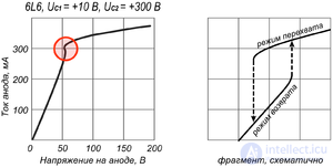
Instrumentally removed I – V characteristics often show a “hysteresis” S-shaped loop in the transition zone, corresponding to a jump-like increase in the anode current with a small increment of the anode voltage. When the anode voltage decreases, the current surge occurs at slightly lower values of current and voltage. The reason for this phenomenon is that in the transition zone with the same value of the anode voltage, two different spatial charge distributions are possible. Sharp, almost instantaneous redistribution of space charge and generate current surges [23] . Amplification cascades are designed so that the lamp always works in the interception mode, so in practice the hysteresis in the transition zone does not matter.
The concentration of cathode current in narrow rays makes radiation tetrodes sensitive to external electromagnetic fields. A strong external magnetic field is able to deflect the beam so much that instead of the inter-turn interval of the second grid, its path will close to the turn of this grid, while the current of the second grid increases, the anode current, output power and efficiency fall, the spectral composition of the distortions changes. According to Morgan Jones, perceptible changes in the spectrum of harmonics can be generated not only by external fields, but also by the residual magnetization of the intra-tube fittings. Own (regular) currents inside the lamp are too weak to affect the residual magnetization - to remove it, you should use external reversing coil with a capacity of 750 W [26] .
The amplification of sound power is historically the first and main field of application of ray tetrodes. In the nomenclature of sound beam tetrodes, lamps designed for relatively low-power (maximum output power not more than 2 W) amplifiers with non-standard filament voltage are distinguished. Direct filament lamps with a filament voltage of 2 V (2P1P, 2P2P, 2P9M) were intended for battery (wearable) radio receivers. Indirectly heated lamps with a filament voltage of 30 V and above (30P1S) were intended for cheap network radio receivers with filament power supply directly from the 110 or 127 V network. Receivers of this type were mass-produced in the USA under the general name "American Five-Lamp" (eng. All-American Five ), they were rare in the USSR.
За исключением вышеупомянутых специализированных ламп, номенклатура лучевых тетродов представляет собой набор конструктивно близких ламп со стандартным напряжением накала 6,3 В, различающихся лишь размерами и предельно допустимыми эксплуатационными параметрами. Лампы одного и того же типа (6V6, 6L6 и т. п. и их клоны) выпускались в разных конструктивных исполнениях с различными пределами рассеиваемой и выходной мощности, поэтому на практике номенклатура тетродов для УЗЧ представляет собой непрерывную линейку ламп. В начале линейки располагаются относительно маломощные лампы семейства 6V6 (советский аналог — 6П6С, аналог в пальчиковом исполнении — 6П1П [27] ). Максимальная мощность, рассеиваемая на катоде 6П6С, ограничена 14 Вт, максимальная мощность, отдаваемая в нагрузку в однотактном усилителе класса А — 5,5 Вт при К НИ =12 % или 4,2 Вт при К НИ =6 % [28] . Двухтактный усилитель на паре 6П6С в классе AB1 способен отдавать в нагрузку до 14 Вт при К НИ =3,5 %. На другом конце линейки располагаются разработанные в 1950-х годах мощные лампы KT88 с максимальной мощностью, рассеиваемой на аноде, в 42 Вт. Двухтактный усилитель на паре KT88 в классе AB1 развивает выходную мощность до 100 Вт при К НИ =2 %. Между этими полюсами расположен ряд ламп средней мощности, некоторые из которых приведены в таблице. Британская лампа KT77 стоит в этом ряду особняком: она была разработана специально для использования в двухтактных усилителях в ультралинейном включении [17] .
|
Indicator |
Unit rev. |
6V6 (6П6С) |
6L6 (6П3С) |
KT66 |
KT77 |
KT88 |
|---|---|---|---|---|---|---|
 |
 |
 |
 |
|||
| Максимальная мощность, рассеиваемая на аноде и на экранирующей сетке |
W |
14 + 2,2 |
19 (для 6L6) + 2,5
20-20,5 (для 6П3С, 6L6G) + 2,5 |
25 + 3,5 |
32 + 6 [17] |
42 + 8 |
| Максимальное постоянное напряжение на аноде |
AT |
350 |
360 в А2.
400 в в А1 ( тестовый режим ) |
500 |
800 [17] |
800 |
| Максимальная мощность двухтактного каскада в классе AB1 (АВ2) в тетродном включении, при нормируемом коэффициенте нелинейных искажений |
Вт, k% |
14 при 3,5 % |
31-32 при 2 % (АВ2)
47 при 2% (АВ2) |
50 при 3-5 % |
— [17]
Ультралинейный 72 при 1,5% |
100 при 2 % |
| Максимальная мощность двухтактного каскада в классе А в триодном включении, при нормируемом коэффициенте нелинейных искажений |
Вт, k% |
18 при 1,2 % [17] |
В послевоенное время выпускались лучевые тетроды, оптимизированные для выполнения особых функций:
В среде конструкторов и любителей существует мнение о том, что в УЗЧ предпочтительнее лампы довоенной разработки (6V6, 6L6, KT66), а ламп послевоенных конструкций и особенно «строчных» ламп следует избегать [32] . Суждение о лучшей линейности ранних звуковых ламп основано на том, что они были оптимизированы под низкие искажения — настолько низкие, насколько позволяла технология. Лампы и усилители тех лет проектировались так, чтобы дать приемлемый уровень искажений минимальным числом ламп без использования обратной связи [33] . Да и сама теория обратной связи только-только создавалась. Удешевление ламп в 1940-е годы изменило конструкторский подход: с использованием глубокой ООС линейность лампы отошла на второй план [32] . Поэтому, например, послевоенный пальчиковый пентод EL84 (6П14П) проигрывает по искажениям довоенному лучевому тетроду 6V6 [34] .
Схемотехника каскадов на лучевых тетродах полностью повторяет схемотехнику каскадов на пентодах. Разница, с практической точки зрения, заключается в согласовании каскада с нагрузкой. Ещё Харрис отмечал, что оптимальное сопротивление нагрузки каскада на «лампе Харриса» должно быть ниже, чем у каскада на эквивалентных пентодах. Тот же подход применяется и к каскадам на «настоящих» лучевых тетродах: оптимальное с точки зрения минимизации искажений сопротивление нагрузки должно быть достаточно низким. С ростом сопротивления нагрузки в спектре искажений возрастает доля нежелательных высших гармоник, поэтому на высоких частотах следует шунтировать головку громкоговорителя RC-цепочкой (цепью Зобеля) [35] . В радиолах со встроенным громкоговорителем тот же эффект достигался шунтированием первичных обмоток выходного трансформатора.
Лучевые тетроды, как и пентоды, могут использоваться в триодном включении — для этого достаточно замкнуть экранирующую сетку на анод. Именно триодный режим использовался в классическом усилителе Вильямсона. Такой усилитель на паре лучевых тетродов KT66 в классе AB1 выдавал в нагрузку 15 Вт выходной мощности [36] . В практике современных однотактных УМЗЧ такой подход применяется редко — в этих усилителях доминируют триоды прямого накала [37] , реже встречаются УМЗЧ на «стабилизаторных» триодах косвенного накала (12AS7, 6C33C, 6C19П).

Comments
To leave a comment
Radio tubes and ion devices
Terms: Radio tubes and ion devices