Lecture
A tetrode is an electron tube having 4 electrodes: a thermionic cathode (direct or indirect heat), 2 grids (control and shielding) and an anode. Invented by Walter Schottky in 1919. Receiver amplification tetrodes were used in radio receiving paths before the mass distribution of pentodes. Generator and modulator tetrodes are still used in power cascades of radio transmitters. Beam tetrodes have found application in the output stages of ULF and are still widely used in guitar amplifiers (less often in high-quality ULF). A special class of devices - electrometric tetrodes also have two grids, but they are fundamentally different from ordinary tetrodes both structurally and in practical application.
One of the very first tetrodes of domestic production, the SB-154 (or 2E1 according to the new classification), had fantastic parameters for those times. The throughput capacity decreased from 5 to 0.005 (!) PF, the internal resistance increased from 30 kΩ to 1.3 MΩ, and the gain exceeded 1000. The shielded lamp immediately and irrevocably forced the triodes out of the radio frequency path and made possible the mass production of direct receiving radio receivers by ranges of long and medium waves (EKL, EFS-2, EES-3, SI-235), which became relatively widespread in the USSR in the mid-1930s. The letter “E” in the names of these receivers meant precisely “shielded”, and the entire name was decoded as follows: shielded, four-lamp, network.
The new tetrodes justified their name “shielded lamp” by the fact that to reduce the influence of external fields on the inside of the balloon a metal film was sprayed or covered with a thin metal mesh connected inside the balloon to the cathode. This tradition has been preserved in the future, and the most modern domestic tetrodes (6E5P, 6E6P, 6E15P) have, in addition to the screen grid, an internal static screen connected inside the lamp to the cathode or having a separate independent output (6E6P).
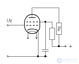
The drawbacks of the triode are the large anode-grid capacity (units of picofarads), which prevents stable amplification at short waves, as well as low gain (up to several dozen). Initially, the designers planned to place a grounded screen between the grid and the anode. In this case, the capacity between the anode and the grid, as it were, was divided into two separate, successively connected capacities: the anode-screen and the screen-grid. Due to the voltage change at the anode, the anode-screen capacitance flows through the capacitance, but then it flows mostly to the ground, and not into the capacitance of the screen-mesh, which has a greater impedance than the screen connects to the ground.
The design of the screen should be such that it does not interfere with the free passage of electrons from the cathode to the anode. Thus, a second screening appeared between the control grid and the anode. When it is connected to the cathode, a low negative potential slows down the electron flow, reducing the already small lamp gain. And when a positive voltage was applied to the screening grid, the electron flow not only did not brake, but also received additional overclocking, increasing the anode current. The grounding of the AC shielding grid eliminated the frequency limitations associated with the throughput capacity.
The dinatron effect is the dislodging of secondary electrons from a metal anode when it is bombarded with electrons and ions; in electron tubes to reduce the harmful effects of the dinatron effect, an anti-dinatron grid is placed; The dinatron effect is used in electron multipliers.
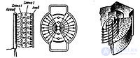
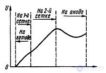
Another innovation was the so-called ray principle of electron flow formation: the control and screen grids of the tetrode were made identical, that is, from the same wire, with the same pitch and number of turns, differing only in the diameters of the ellipse. At the same time, the grids were mounted on the fixing cross-arms in such a way that the turns of the screen grid were located exactly against the turns of the control grid and “hid” behind its turns. As a result, electrons on the way to the anode "skirted" the turns of the screen grid, not settling on it and not creating a constant screen current. At the same time, electrons “compressed” into narrow beams increased the electron flux density to such an extent that a virtual region formed between the screen grid and the anode, which has a potential below the anode and prevents the oncoming (“dinatron”) electron flow.
In the places where the grids are attached, the traverses, as it were, block the path to the electron flow, thereby distorting the general “beam” character of the anode current. To eliminate this effect on the overall anode characteristic, special solid metal plates are installed at the places of installation of the cross-arms between them and the anode, which bar off the cross-bars from the anode, and the anode itself in these places is made with a U-shaped bend to increase the distance between it and the screen grids . Such a peculiar shape of the anode is a sure sign of ray lamps. These additional shielding plates are always connected inside the lamp with a cathode having zero potential, which additionally contributes to the creation of a virtual area between the anode and the screen grid.
Beam tetrodes were created specifically for power amplification cascades and were used in terminal ULF cascades, television sweeps and transmitters. In modern industrial and amateur practice, output beam tetrodes, developed specifically for ULF - 6P6S (analogue 6V6) and 6P3S (analogue 6L6), are most common. 6P27S, the Soviet functional analogue of the famous EL34 pentode, is a ray tetrode. Specific types of ray tetrodes (6P7S, 6P13S) have been optimized for powerful lower-level scanning cascades and can also work in ULF output stages. Separate low-power beam tetrodes were designed to amplify high frequencies and can work effectively in triode switching (6G4P).
A special type of four-electrode lamp, in which the fourth electrode is a cathode or protective grid, is designed to increase the steepness of the anode characteristic at extremely low anode voltages.
Electrometric lamps are designed to register and amplify extremely small (10 −15 .. 10 −10 A) currents, for example, output currents of mass spectrometers, star photometers, etc., of ultra-sensitive measuring equipment. The best galvanometers register currents from 10 −12 A. Conventional lamps are also useless in the range of such small currents, since the own grid current of receiving-amplifying lamps in the best conditions is about 10 −9 A. To reduce the grid currents, a number of technological methods were developed:
At such low anodic voltages, especially at low cathode temperatures, the steepness of the lamp is unacceptably low. To increase the slope, an additional cathode grid is introduced between the control grid and the cathode, to which a positive potential of several volts is fed. As a result, the electron cloud around the cathode expands, the effective diameter of the radiating surface increases, and with it the steepness. In electrometric tetrodes, it ranges from 20 to 300 microamps per volt. In this case, the working anode current of the lamp is from tens to hundreds of microamps. In schematic diagrams, the electrometric tetrode is depicted in the same way as an ordinary tetrode, but the second grid (counting from the cathode) is the controlling one .

Comments
To leave a comment
Radio tubes and ion devices
Terms: Radio tubes and ion devices