Lecture
Electrovacuum diode - vacuum two-electrode electron tube. The cathode of the diode is heated to temperatures at which thermoelectronic emission occurs. When a negative voltage is applied to the anode relative to the cathode, all electrons emitted by the cathode return to the cathode, when a positive voltage is applied to the anode, a part of the emitted electrons rush to the anode, forming its current. Thus, the diode rectifies the voltage applied to it. This property of the diode is used for rectifying alternating current and detecting high frequency signals. The practical frequency range of a traditional vacuum diode is limited to frequencies up to 500 MHz. Disk diodes integrated into waveguides can detect frequencies up to 10 GHz [1] .

Indication on the diagrams of the diode with the cathode of indirect heating.
An electrovacuum diode is a vessel (balloon) in which a high vacuum is created. The cylinder placed two electrodes - the cathode and the anode. The direct filament cathode is a straight or W-shaped filament heated by the filament current. The indirectly heated cathode is a long cylinder or duct, inside of which is placed an electrically insulated heater coil. As a rule, the cathode is embedded inside a cylindrical or box-shaped anode, which in power diodes can have edges or "wings" for heat removal. The terminals of the cathode, the anode and the heater (in lamps of indirect heat) are connected to external terminals (lamp legs).
When the cathode is heated, the electrons will begin to leave its surface due to thermionic emission. The electrons leaving the surface will prevent other electrons from ejecting, as a result a kind of electron cloud is formed around the cathode. Part of the electrons with the lowest velocities from the cloud falls back to the cathode. At a given cathode temperature, the cloud stabilizes: as many electrons fall on the cathode as it flies out of it.
Already at zero anode voltage relative to the cathode (for example, when the anode is short-circuited to the cathode) a current of electrons from the cathode to the anode flows in the lamp: relatively fast electrons overcome the potential space charge well and are attracted to the anode. Current cut-off occurs only when a negative negative voltage of about −1 V and lower is applied to the anode. When a positive voltage is applied to the anode in the diode, an accelerating field arises, the anode current increases. When the anode current reaches values close to the cathode emission limit, the current increase slows down and then stabilizes (saturates).
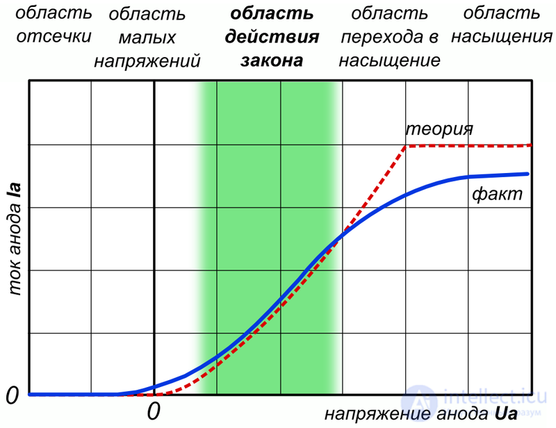
Plots of the current-voltage characteristics of the diode
Volt-ampere characteristic (VAC) of an electrovacuum diode has 3 characteristic sections:
1. Nonlinear plot . At the initial part of the I – V characteristic, the current slowly increases with increasing voltage at the anode, which is explained by the counteraction of the anode field of the volume negative charge of the electron cloud. Compared to the saturation current, the anode current at  very small (and not shown in the diagram). Its dependence on voltage grows exponentially, which is caused by the spread of the initial electron velocities. For the complete cessation of the anode current, it is necessary to apply some anode voltage less than zero, called a blocking voltage.
2. Plot of law of degree three second . The dependence of the anode current on the voltage is described by the law of the degree of the second two:
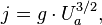
where g is a constant depending on the configuration and size of the electrodes (perveance). In the simplest model, perveance does not depend on the composition and temperature of the cathode, in fact it increases with increasing temperature due to uneven heating of the cathode.
3. The site of saturation . With a further increase in the voltage at the anode, the current increase slows down and then stops completely, since all electrons emitted from the cathode reach the anode. A further increase in the anode current at a given filament is impossible, since this requires additional electrons, and there is no place to take them, since all the emission of the cathode is exhausted. The steady-state anode current is called the saturation current . This plot is described by the Richardson-Dushman Act:
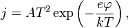
Where 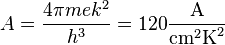 - universal thermoelectronic constant Sommerfeld.
The IVC of the anode depends on the filament voltage - the greater the heat, the greater the slope of the IVC and the greater the saturation current. An excessive increase in the filament voltage leads to a decrease in the lamp life.
The main parameters of the electrovacuum diode include:
 - change of anode current in mA per 1 voltage change.
The slope and internal resistance are functions of the anode voltage and the temperature of the cathode.
If the temperature of the cathode is constant, then within the range of the "three second" slope is equal to the first derivative of the "three-second" function.
Electrovacuum diodes are marked on the same principle as other lamps:
If the fourth element is missing, then it indicates the presence of a metal case!
Compared with semiconductor diodes in electrovacuum diodes there is no reverse current, and they withstand higher voltages. Racks to ionizing radiation. However, they are much larger and less efficient.
|
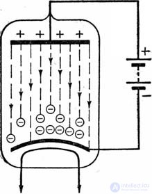
Let us consider in more detail the processes in the anode circuit of the diode (as applied to the circuits in Fig. 8-2 , b or 8-4 ). Suppose initially that the anode voltage is missing, i.e. the anode is shorted to the cathode. The electrons emitted by the cathode remain in space around the cathode, since their further movement in a vacuum is prevented by the repulsive action of previously emitted electrons. Thus, a “cloud” of electrons is formed around the cathode; the set of charges of these electrons is called the volume (or spatial ) charge. The space charge density, i.e. the average number of electrons per unit volume increases with increasing temperature of the cathode. At a given (say, normal) temperature, the space charge density is preserved, since the electron cloud inhibits the motion of newly emitted electrons, returning them to the cathode. Separate electrons emerging from the cathode with a high initial velocity can reach the anode and introduce some initial current in its circuit (ie, the current in the absence of anode voltage); however, this current is not sufficient for practical use. When a battery (or another constant voltage source) is connected to the anode circuit, creating a positive potential at the anode with respect to the cathode, an electric field arises; Some of the lines of force of this field can be imagined ending in a space charge electrons, and these electrons acquire an accelerated motion towards the anode ( Fig. 8-5 ). Anode current occurs; as the anode voltage increases, the current increases and the space charge density decreases. At a sufficiently high voltage at the anode, the decelerating field disappears and all the electrons, flying out from the surface of the cathode, immediately enter the accelerating field, under the action of which they all reach the anode. A further increase in the voltage at the anode does not cause an increase in current. Comes saturation mode . In this mode, the anode current I a is equal to the total emission current I e . |
||||
|
||||
|
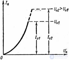
If the temperature of the cathode is increased (within acceptable limits, of course), then due to an increase in the energy of movement of electrons in the metal, the space charge density around the cathode also increases. In this case, the saturation mode will be reached at a higher value of the anode voltage and the saturation current I e will increase. The theoretical dependence of the anode current I a on the voltage at the anode U a (at two filament voltages U n1 and U n2 ) is given in Fig. 8-6 . |
||||
|
||||
|
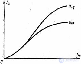
It is possible to remove the dependence of the anodic current on the anode voltage experimentally, by changing the voltage in jumps using a divider (potentiometer) and each time counting the amount of current. This dependence, represented graphically, is called a diode characteristic. The shape of the practically taken characteristics, generally following the theoretically stipulated course, has some features mainly in the upper part ( Fig.8-7 ): the characteristics do not have a sharp transition to saturation currents, and in the saturation region there is still a rise in characteristics. This is explained, firstly, by the disappearance of the space charge, as a result of which the electric field lines of the anode end in the saturation region directly at the cathode and, by facilitating the electron output, slightly increase the emission. This is the main reason for the smooth bending of the characteristics of a diode with a tungsten cathode, for which it is still possible to approximately name the value of the saturation current. The second reason for the increase in the emission current with increasing anode voltage is especially characteristic of lamps with oxide cathodes: the oxide layer is additionally heated by the anode current passing through it and gives emission not only from the surface, but also from the coating depressions. In these lamps, the saturation current cannot be detected at all, and the growth of the anode current has to be limited to a value that is safe for the cathode, but is on the rise of the characteristic. |
||||
|
||||
|
The electrical circuit in which the diode is included does not obey Ohm’s law: first, when the sign of the anode voltage changes to a reverse current in the circuit, it stops; secondly, even in the area of positive voltages, the current changes disproportionately to the voltage ( Fig.8-7 ). Devices that violate the proportionality (straight-line relationship) between voltage and current are called non-linear . Hence, the diode must also be attributed to the number of nonlinear devices. For a conventional conductor in a DC circuit, the only value characterizing the ratios of the currents in this conductor and the voltages applied to it is resistance (or its inverse is conductivity). Resistance can be called a linear circuit parameter. You can enter an idea about the parameters for a non-linear conductor, in particular for a diode. This parameter is the internal resistance of the diode . You can measure the voltage between the anode and the cathode with a voltmeter, and the current through the anode-cathode gap with an ammeter. The ratio of voltage to current will be the internal resistance of the diode for direct current. But considering any of the above characteristics of the diode, we can verify that this resistance is not a constant value, which is characteristic of a nonlinear device. Indeed, at negative voltages at the anode, the current is zero. This means that in this region the resistance is infinite (and the conductivity is zero). At positive anode voltages, however, the resistance of the direct current will be different for different points of the characteristic due to its curvilinearity. |
||||
|
||||
|
In fig. 8-8 , and for point A of the characteristic resistance to direct current |
||||
|
||||
|
There are also possible cases where, in addition to the constant voltage E a , an alternating voltage with amplitude acts on the anode of the diode |
||||
|
||||
|
The internal resistance of the diode for alternating current (or, as they call otherwise, the differential internal resistance ) is the ratio of the increase in the anode voltage to the corresponding increase in the anode current. Icon The method of constructing the time diagram of the anode current shown in Fig. 8-8 , b , is called the construction of the current by sweeping the anode voltage on the diode characteristic. Due to the curvature of the characteristic curve, depicting in time the magnitude of the current may be distorted compared with the curve depicting the voltage. This type of distortion is called non-linear . In different areas of the characteristics of the internal resistance is different, and we can only speak strictly about the average value of the internal resistance for a particular area of finite length. However, the main part of the real characteristics of the diode is almost straightforward. On this part of the characteristic, the differential internal resistance is approximately constant. This value is usually called as a parameter of the diode. To determine the internal resistance there is no need, of course, to build a sweep (similar to Fig. 8-8 , b ). You can use the construction shown in Fig. 8-8 , and . On the characteristic stands out the area bounded by the voltage U a 1 and U a 1 + |
||||
|
||||
|
So for example, if for |
||||
|
||||
|
The AC resistance on the straight section of the diode characteristic is less than the DC resistance, which is easy to show with an example ( Figure 8-8 ). The relationship between voltage and current increments can be estimated by another parameter, which is called the slope of the diode and corresponds to the internal conductivity of the diode for alternating current. Steepness is the reciprocal of internal resistance: |
||||
|
||||
|
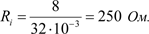
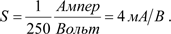
If the internal resistance is in ohms, i.e. in volts per amp, the steepness would have to be calculated in "reverse ohm", i.e. in amperes per volt. However, for practical convenience, it is customary to calculate the slope in milliamperes per volt (mA / V). The steepness of the characteristic is the ratio of the increase in the anode current to the increase in the voltage at the anode that caused it; numerically, it shows how much milliamps anode current will increase if the voltage at the anode is increased by 1 V. So, if R i = 250 Ohm , then the slope |
||||
|
||||
|
Следовательно, крутизна не является независимым параметром диода: если задано внутреннее сопротивление, то тем самым задана и крутизна. Ее можно определить и из характеристического треугольника ( рис. 8-8 , а ). Так же, как и внутреннее сопротивление, крутизна непостоянна для разных участков характеристики. В области отрицательных анодных напряжений она равна нулю. За параметр лампы принимают значение крутизны, соответствующее ее прямолинейному крутому участку, в пределах которого крутизна имеет наибольшее и почти постоянное значение. При технических расчетах иногда бывает допустимым изображать приближенно характеристику диода в виде прямой линии, исходящей из начала координат в положительную область анодных напряжений. Для такой идеализированной характеристики существует единственное значение параметра R i (или S ); в области же отрицательных напряжений внутреннее сопротивление равно бесконечности (крутизна равна нулю). Следовательно, диод, имеющий такую характеристику, все же остается нелинейным, обладающим односторонней проводимостью. При разработке аппаратуры ультракоротких волн наряду с внутренним сопротивлением диода приходится интересоваться его "паразитным" параметром - емкостью между анодом и катодом C a.к. . Эта емкость неизбежна как результат взаимного геометрического расположения этих двух электродов вместе с их выводами. Но вместе с тем эта емкость нежелательна, так как ее проводимость Следующим параметром диода, важным при определении желательного режима его работы, оказывается допустимая мощность рассеяния на аноде P а.макс. . Мы знаем, что каждый электрон при ударе об анод отдает на его нагревание энергию, равную произведению заряда e на напряжение U а . Если за секунду достигают анода N электронов, то общая энергия, отдаваемая ими, как раз равна мощности, расходуемой на нагрев анода, |
||||
|
||||
|
где N·e = I a (заряд, проходящий через сечение цепи за секунду). Мощность P a можно увеличивать лишь до того предела, пока нагрев анода не окажется опасным для лампы (анод плавится, выделяет газы и даже дает дополнительный нагрев катода). Эта максимально допустимая мощность и указывается в качестве параметра диодов, применяемых в выпрямителях. Их режим должен удовлетворять условию P a < P a.макс . В маломощных диодах радиоприемных устройств нагрев анода учитывать не требуется, так как он всегда ниже допустимого. Для увеличения допустимой мощности при изготовлении ламп принимают конструктивные меры к охлаждению анодов: выполняют их из черненого никеля, дающего хорошее теплоизлучение, с ребрами, увеличивающими площадь охлаждения. В лампах большой мощности применяется искусственное воздушное или жидкостное охлаждение. Для высоковольтных электровакуумных приборов дополнительным эксплуатационным параметром является наибольшее допустимое обратное напряжение U обр.макс . Дело в том, что если диод в процессе работы нагрелся до высокой температуры, то с поверхности анода может возникнуть термоэлектронная эмиссия, способная дать ток в обратном направлении при больших отрицательных напряжениях на аноде. Это приводит к пробою диода между анодом и катодом, чего допускать нельзя. Важнейший эксплуатационный показатель радиолампы - ее долговечность зависит, очевидно, не только от сохранности свойств катода. Если какой-либо из перечисленных нами параметров в процессе эксплуатации (или хранения) лампы оказался хуже допустимого значения, то лампу приходится браковать. Поэтому долговечностью (или сроком службы) электронного прибора считают время работы, по истечении которого один из основных параметров выходит за пределы установленных значений или же прибор становится непригодным к нормальной эксплуатации по другим причинам. |
||||
|
||||
|
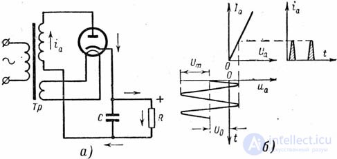
Для иллюстрации применения диода (кенотрона) рассмотрим схему простейшего выпрямителя, который используется для питания постоянным (выпрямленным) током нагрузочного (потреб***яющего) сопротивления ( рис. 8-9 , а ). Источником питания служит сеть переменного тока, в которую включен трансформатор Тр своей первичной обмоткой. Одна из двух его вторичных обмоток питает накал кенотрона, а другая создает переменное напряжение в анодной цепи. Ток через кенотрон протекает только при положительном анодном напряжении. Направление этого тока - от анода к катоду внутри кенотрона и далее через сопротивление R . Следовательно, через сопротивление R , как и через кенотрон, должны были бы проходить импульсы тока и создавать на этом сопротивлении пульсирующее, а не постоянное напряжение. Чтобы через нагрузочное сопротивление протекал лишь постоянный ток, параллельно этому сопротивлению включают конденсатор C в роли простейшего фильтра. Идеализируя работу фильтра, мы можем сказать, что между анодом и катодом кенотрона действует не только переменное напряжение вторичной обмотки трансформатора, но и постоянное напряжение, падающее на сопротивлении R и обращенное на анод своим отрицательным знаком. Такая идеализированная картина работы выпрямителя развернута на рис. 8-9 , б . Характерно то, что импульс тока через кенотрон длится меньше полупериода: ток может проходить только в те промежутки времени, пока положительное напряжение от трансформатора больше по абсолютной величине, чем постоянное напряжение U 0 , падающее на нагрузке (сопротивлении R ). В течение отрицательного полупериода напряжение от трансформатора суммируется с напряжением на нагрузке. Чтобы кенотрон не был пробит, сумма U 0 + U m не должна превышать допустимой для него величины обратного напряжения. Полезное (выпрямленное) напряжение равно произведению постоянной составляющей тока на нагрузочное сопротивление. Такой выпрямитель, импульсы через который появляются лишь за одну половину периода питающего напряжения, называют однополупериодным . |
||||
|
||||
|
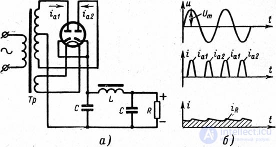
Более совершенна двухполупериодная (двухтактная) схема выпрямителя, требующая двух кенотронов или одного двойного кенотрона ( рис. 8-10 , а ). Здесь оба диода работают поочередно на общее нагрузочное сопротивление R . Вывод к нагрузочному сопротивлению взят от средней точки повышающей вторичной обмотки трансформатора. In fig. 8-10 , б представлены диаграммы напряжения и токов в анодных цепях и сопротивлении R . Аноды кенотрона питаются от двух разных половин повышающей обмотки трансформатора; когда напряжение положительно для первого анода, оно отрицательно для второго, и наоборот. Импульсы тока следуют через диод в течение каждого полупериода, причем в сопротивлении R эти импульсы направлены всегда в одну сторону - от катода к анодам. Преимущество двухполупериодной схемы состоит в том, что импульсы тока в ней следуют один за другим в два раза чаще, чем в однополупериодной. Это облегчает задачу фильтрации. Для более совершенной фильтрации на схеме изображено П-образное звено фильтра нижних частот. |
||||
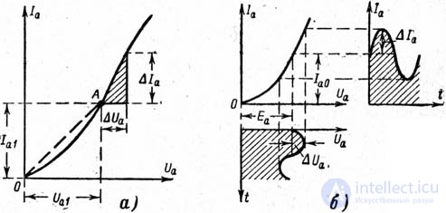

 U a . In fig. 8-8 , b, the varying voltage is developed along the time axis t down. In this case, a pulsating current passes through the anode circuit, which contains both a constant I a0 and a variable

 C a.к. на сверхвысоких частотах может заметно шунтировать диод, уменьшая его выпрямительный эффект. В диодах, предназначаемых для ультракоротких (хотя бы метровых) волн, емкость C a.к. исчисляется немногими единицами пикофарад. Для кенотронов (диоды, предназначенные для выпрямителей) этот параметр несуществен.
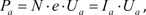

Comments
To leave a comment
Radio tubes and ion devices
Terms: Radio tubes and ion devices