Lecture
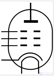
Conditional graphic designation of indirectly heated pentode. Top down:
• anode,
• anti-inatron mesh,
• screening mesh
• control grid
• cathode and
• heater (two leads).
Pentode (from the ancient Greek πέντε five, according to the number of electrodes) is a vacuum electron lamp with a shielding grid in which a third (protective or antidynamic) grid is placed between the shielding grid and the anode, which suppresses the dinatron effect. As a rule, in direct-glow lamps, the third grid is connected to the midpoint of the cathode, in indirect-glow lamps - to any point of the cathode [1] [note 1] . In most pentodes, the third grid and cathode are connected inside the cylinder, so they have only four signal leads. In the historical literature, pentodes in the strict sense called such four-output lamps, and pentodes with a separate conclusion of the third grid were called “three-grid lamps” [2] . By design and purpose, pentodes are divided into four main types: low-power high-frequency amplifiers, output pentodes for video amplifiers, output pentodes of low-frequency amplifiers, and powerful generator pentodes [3] .
Screened lamps - tetrode and pentode - surpass the triode at high frequencies. The upper working frequency of the pentode amplifier can reach 1 GHz [3] [note 2] . Pentode differs favorably from the tetrode by the absence of a drop-down section of the current-voltage characteristic, resistance to self-excitation, and smaller nonlinear distortions [4] . Pentodes tend to have a high output impedance - in most of the working anode voltages, pentodes are equivalent to controlled current sources. The efficiency of the power amplifier on the pentodes (about 35% [5] ) is significantly higher than that of the amplifier on triodes (15% -25% [5] ), [note 3] but slightly lower than that of the amplifier on radiation tetrodes [note 4] .
The drawbacks of pentodes (and in general of all shielded lamps) are higher nonlinear distortions than the triode, in which odd harmonics dominate, the sharp dependence of the gain on the load resistance, a greater level of intrinsic noise [5] .
In 1906-1908, Lee de Forest invented the first amplifying lamp, the triode [6] . Erroneously assuming that the conductivity of the triode is due to the ion current of the gas discharge, the inventor did not try to create a deep vacuum in the bulb of his lamp. On the contrary, having discovered that his primitive mercury vacuum pump was contaminating the balloon with mercury vapor, De Forest switched to experiments with mercury lamps. Austrian Robert von Lieben developed his design of mercury triode with an oxide cathode, and in 1913 brought the power of the triode radio transmitter to 12 W at a wavelength of 600 m [7] [note 5] . In the same year, 1913, de Foresta acquired AT & T. Harold Arnold, who worked for the corporation, understood that a high vacuum was necessary for the stable work of the “repeater” de Forest, and within a year brought the first practical vacuum triode to the serial production - a repeater for telephone lines [8] . Child (1911), Langmuir (1913) and Schottky (1914) developed a space charge model — a mathematical apparatus that describes the behavior of vacuum tubes [7] [9] . From the theory followed the conclusion confirmed by practice that the limiting frequency of the amplification of the f diode amplifier is limited by the effect of its pass-through capacitance C ac :
f pr ~ S / Cac ,
where S is the slope of the grid-anode characteristic [note 6]
.
The triode turned out to be suitable only for work on sound frequencies, long and medium radio waves. To reach the shortwave range, the throughput of the lamp had to be drastically reduced. In 1926, Albert Hull solved the problem by placing an additional screening grid between the control grid and the anode of the triode. Henry Round (Eng.) Russian, who worked at Marconi (Eng.) Russian., First brought the idea of Hull to mass production, and in 1927, radio frequency tetrodes entered the market with a pass capacity of no more than 0.025 pF [10] .

Miniaturization of pentodes. From left to right:
* KF4 (Germany, 1935) [11]
* R207 (USA, 1935) [12]
* 1T4 (United States, 1939) [13]
* 1ZH18B (USSR, 1950s - rod lamp, which has no analogues in the West)
* On the right, for clarity, a TO92 transistor.
Regardless of Hull and Round, a group of Philips Physical Laboratory (nid.) Rus. Worked on many-electron lamps. under the direction of Gilles Holst (nid.) Russian .. In contrast to the Americans, the Dutch were not interested in radio frequencies, but in high-quality reproduction of sound frequencies [14] and improving the efficiency of lamps [15] . The tetrode, which is by nature non-linear due to the irreducible year of the spin effect, was of little use for this task [note 7] . In order to suppress the dinatron effect, Bernard Tellegen placed between the screening grid a third grid electrically connected to the cathode. This grid was relatively rare and had almost no effect on the primary flow of electrons from the cathode to the anode, but effectively blocked the current of the secondary electrons from the anode to the shielding grid. The round came to the same idea in the same year of 1926, but the championship already belonged to Tellegen, and the patent for the invention came from Philips [14] .
Philips licensed production of pentodes worldwide and entered into a strategic partnership with Bell Labs [16] . In 1931, RCA in the USA and KO Vacuum Tube in Japan began serial production of low-frequency pentodes [17] . In 1932, RCA released the first radio frequency pentodes type 57 and type 58 [14] . Already at the beginning of 1932, amateur constructions on pentodes were massively published in the USA [18] . EMI (United Kingdom) did not want to buy Tellegen's patent, which was considered one of the most valuable developments by Philips [19] , and instead created an alternative to the pentode — a beam tetrode [20] [21] . The development of powerful lamps was divided into two branches - the beam tetrode in the USA and the UK, pentode in continental Europe [22] .
The similarity of the electrical properties of beam tetrodes and powerful amplifying pentodes has led to a mixture of these terms in the literature. The same lamp can be called both the beam tetrode and the pentode - despite the fundamental differences in the internal structure of these types of lamps [23] . Thus, in the reference book of Katsnelson and Larionov in 1968, the 6P1P radiation tetrode is called a pentode , while the attached figure shows radiation-producing plates that are not characteristic of pentode [24] . In the reference book of the State Power Publishing House of 1955, 6P1P is called the ray tetrode [25] . The same happened in the English-language literature: the PCL82 combined lamp (the Soviet analogue is 6F3P [26] ) in the technical documentation of Thorn-EMI is classified as a “triode - beam tetrode”, in the Mullard documentation as a “triode - pentode” [23] .
The peak of innovation in electrovacuum technology fell on 1934 - this year, manufacturers threw on the market the maximum number of new developments [8] , including the first radio-frequency acyclic pentodes type 954 and type 956 [27] . There has been a transition of stationary equipment from the heating voltages of 2.5 V and 4 V to a voltage of 6.3 V [28] [29] . The development of multi-electrode and combined lamps continued - RCA brought a heptod (pentagride) to the market, Telefunken produced an octode and a triode-hexode [28] .
In the postwar years, pentodes developed evolutionarily. In 1950-1952, the transition from octal lamps to miniature "finger" lamps with nine pins began [30] [31] [note 8] . In 1953 they became the standard of NATO, by 1958 almost the entire [note 9] nomenclature of mass receiving-amplifying lamps was released in a new construct, [30] by 1960 the share of metal lamps with an octal base in the USSR decreased to 20% of the total output [32 ] . New developments have been optimized to achieve maximum efficiency, sometimes to the detriment of linearity (for example, EL84 (Eng.) Russian., Which has lost in linearity to its predecessors) [33] .
The latest generation of radio tubes, subminiature nuvistors, was released by RCA in 1960 [34] , but it did not find mass use outside the MIC. There was no pentode in the American nuvistor series [35] , and in the USSR a pentode-nuvistor 6Ж54Н was produced. The USSR also developed its own unique [36] class of lamps - subminiature rod lamps designed by V.N. Avdeev, in which instead of the traditional twisted grids used rigid rods oriented along the cathodes [37] .
Depending on the functions performed, broad-use pentodes can be divided into four types, and within the most numerous type (high-frequency low-power pentodes), special subtypes can be distinguished by function [3] . Each field of application set special priorities for designers, and for their implementation each type of pentodes found its own design features.
| N | Type of | Application | Criterion of development | Design features | Examples |
|---|---|---|---|---|---|
| 1A | Low-power high-frequency, narrowband pentodes | Amplification of voltage in resonant cascades with a narrow bandwidth [38] , for example, cascades of frequency loops with superheterodyne | Minimum possible throughput capacity at (preferably) high slope [38] (from 2 to 10 mA / V) | Thick shielding mesh. Careful shielding of conclusions (reduction of interelectrode capacitances). Suppression of anode edge margin [39] | 6Ж1П (photo), 6Ж45Б [39] |
| 1B | Low-power high-frequency, broadband pentodes | Increased voltage down-to-good cascades with a wide bandwidth (television, radio relay communication) [39] | Maximum high slope [40] (from 10 to 30 mA / V) | The minimum possible distance from the cathode to the first grid, thick winding of the first grid (6Ж9П - winding step 17 turns / mm) on the frame frame, gilding of the first grid. Low cathode operating temperature, special smooth cathode coatings [41] . As a consequence - the highest cost among all types of pentodes [42] |
6ZHP, 6ZH11P [42] |
| 1B | Low-power high-frequency pentodes of variable curvature (vari-mu, pentodes with an extended characteristic, [43] , pentodes with a remote cut-off [note 10] ) | Automatic gain control circuits [42] | Nonlinear slope of the anode-grid characteristic (ACX is stretched to the area of negative voltages). Moderate bandwidth requirements [42] . | Variable spacing of the turns of the first grid [44] . As a consequence, increased nonlinear distortions [45] . |
6K4P, 6K13P [44] |
| 1G | Dual control low power pentodes | Frequency converters, signal mixers [46] | Effective control of the current of the anode on the third grid [46] | Moderately thick winding of the third grid, a separate conclusion of the third grid [46] | 6J46B [47] |
| 2 | Video Pentodes | Increasing the voltage and power of the video signal (from tens of Hz to several MHz) when operating on resistive loads [48] | Maximum range of output voltage at a given power mode. High slope characteristic at relatively high (tens of mA) operating currents [48] | Similar to broadband HF pentodes, corrected for greater power dissipation [49] | 6P15P [49] |
| 3 | Output low-frequency (sound) pentodes | Output stages of audio frequency amplifiers operating without grid currents [49] | Small nonlinear distortions at high output power, a shift of the anode-grid characteristic to the left, optimization of work at high voltages on the shielding grid [49] . | 
The relatively rare spirals of the EL84 low-frequency pentode are not a targeted solution, but a consequence of reasonable savings: the high slope of the characteristics in the ULF is not needed [50] . Rare winding control grid, even less dense winding of the second and third grid. Powerful cathode, anode and bearing armature fittings [50]As a result, a relatively low output impedance and a smooth, wide transition zone from the return mode to the intercept mode [51] . |
6P33P [51] EL84 (6P14P) |
| four | Powerful high-frequency (generator) pentodes | Generator lamps of high-power radio transmitters (up to several hundred kW) [52] | Maximum generator efficiency with stable thermal conditions [52] | Efficient heat dissipation, especially with grids. When working with single-band modulation - small signal distortion [52] . | GU-81 [52] (photo) |

Normalized current distribution in the pentode (current-voltage characteristic I K = I a + I c2 ).
In normal operation, the third grid of pentodes is connected to the cathode, a constant negative bias voltage U C1 is applied to the first (control) grid, a constant positive voltage U c2 equal to or less to the cascade supply voltage is supplied to the second (shielding) grid. Electrons emitted by the cathode (cathode current I K ), in this mode, there are only two ways - from the cathode to the screening grid (screen current I c2 ), and from the cathode to the anode (current anode I a ). The cathode current is almost independent of the anode voltage U a : it is determined only by the voltages on the control and shield grids [53] . The extremely simplified formula for the cathode current is reduced to the IVC of the equivalent diode according to Child-Langmuir law: [note 11]
I K ~ (U C1 + DU c2 ) 3/2 [54] ,
where D is the relative permeability (a measure of the effectiveness of control over the first grid).
Real pentodes can have a more acute dependence of I K on control voltages (degree more than 3/2) [54] and a small blockage in the region of particularly small U a . In practice, the distribution of the cathode current between the screen and the anode (the fraction of the cathode current reaching the anode) at constant U C2 is of greater importance. The graph of this distribution has two approximately linear sections of different steepness, separated by a clearly observed fracture [55] :

In the tetrode (above), secondary electrons knocked out of the anode are attracted to the screen grid, reducing the anode current. In the pentode (bottom), they are returned to the anode.
As in the tetrode, the bombardment of the anode with electrons with an energy of more than 10 ... 15 eV generates secondary emission from the anode [60] . In the tetrode, in the return mode, the secondary electrons move freely to the screening grid, reducing the anode current. In the early tetrodes, the anode current could even change direction (the reverse current of the secondary electrons exceeded the forward current) [61] . In the pentode on the way from the anode to the screen an obstacle is placed - the third grid. It is not able to detain fast primary electrons, but it effectively prevents the reverse current of slow secondary electrons [4] . The diatron effect in pentodes characteristic of tetrodes is suppressed: with increasing U a, the current-voltage characteristics of pentodes increase monotonically [4] .
At low frequencies ( f << F gr ) the gain of the pentode with an active anode load is determined by the slope of the lamp S and the load resistance R n :
K = SR n [62]
The same formula applies to reactive load. With comparable values of load resistance and internal resistance of the pentode R a , the equivalent generator resistance R equ = R a R n / (R a + R n ) should be substituted into the formula [63]
In the high-frequency region, a pentode with a resistive load [64] is characterized by a broadband ratio ( γ ) indicator — the product of the frequency and the gain achievable at this frequency. The broadband coefficient does not depend on the active resistance of the load, but decreases with an increase in its capacity C n :
γ = K Δ f = S / (2π (C out + C in + C n )) [40] [65]
The broadband ratio of the mass pentode series lies in the range from 50 to 200 MHz [66] . Table values of the coefficient are indicated either for the ideal case C n = 0, or for some standard C n . Для пальчиковых ламп принимается C н =5.5 пФ, поэтому справочные значения коэффициента различаются несущественно [67] . Для октальных ламп принимается C н =10 пФ, поэтому их коэффициент широкополосности под нагрузкой примерно в полтора раза ниже «безнагрузочного» коэффициента [68] [69] .
In pentode amplifiers without frequency correction, the broadband ratio should exceed the upper limit of the amplified frequencies by 5 ... 10 times, in amplifiers with frequency correction - by 2.5 ... 4 times [70] . This limit for the most advanced basement pentodes does not exceed 200 MHz [71] . Replacing the active load with a narrowband resonant circuit allows us to bring the upper working frequency of acorn pentodes (1Ж1Ж) and individual finger lamps (6K1P) to 500 MHz [72] . A further increase in the operating frequency of a single cascade is impossible due to the unacceptably high noise of the pentodes [72] . The operating frequency of the broadband cascade can be increased by several times by parallelizing the amplification cascade and loading its anodes onto the traveling wave line. Such a cascade with a traveling wave (otherwise, a cascade of distributed amplification ) on n lamps has a cut-off frequency that is n times greater than the cut-off frequency of a single pentode [73] . (in a limit to 1 GHz). In practice, the number of lamps in a cascade was limited to six or eight [74] . The traveling wave tube cascades were expensive, required fine tuning, and therefore were completely superseded by solid-state microwave amplifiers.
 |
 |
 |
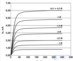
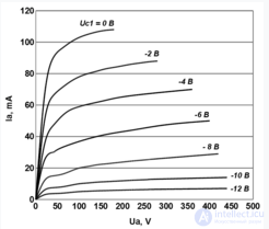
| Low-power pentode (6F32P) | Powerful LF Pentode (6P14P) | Reference: powerful beam tetrode (KT88 (English) Russian.) |
Anode current-voltage characteristics (VAC) of low-power pentodes are close to ideal: a sharp transition from the return mode to the intercept mode occurs at relatively low U a ; flat “shelves” of the current – voltage characteristic indicate a high output resistance (6F32P - 2.5 MΩ in nominal mode [75] ). This allows building almost perfect differential cascades [76] and active loads (stable current sources) [77] on the pentodes. In powerful pentodes, the output impedance is relatively low, and the transition to the interception zone is stretched. At low anodic voltages and a large negative bias of the control grid, there is a “tetrode” nonlinearity of the I – V shelf.
Qualitative analysis of IVC of pentodes shows that
The human ear is tolerant of even harmonics, but very sensitive to the ringing of odd harmonics that prevail in the spectrum of pentode distortions [79] . LF power amplifiers on pentodes can reach an acceptable level of audible distortion only at very low measurable TO NI , which can only be achieved if the amplifier is covered by deep negative feedback (OOS) [79] . Amplifiers on triodes, on the contrary, provide acceptable sound quality without using general feedback. Beam tetrodes occupy an intermediate position: they also need OOS, but their spectrum of distortions is closer to the triode [81] .
In modern tube-based ULFs of the initial level, pentodes of post-war development EL34 (English) Russian are widely used. and EL84 (Eng.) Russian. (analog - 6P14P [82] ). However, in high-quality musical ULF, pre-war direct-heat triodes are preferable, while in guitar ULF, pre-war ray tetrodes are preferable. The latter is probably due to the historical division of the market into “European pentodes” and “American ray tetrodes” [83] . Opinion about the best linearity of the lamps of the pre-war development is explained by the fact that they were optimized for low distortions - as low as the technology allowed [84] . “Gain was expensive” (Morgan Jones), so the lamps and amplifiers of those years were designed to give an acceptable level of distortion with the minimum number of lamps without using feedback [85] . Yes, and the feedback theory itself was just being created. The cheapening of lamps in the 1940s changed the design approach: using deep OOS, the linearity of the lamp faded into the background [84] [33] . Therefore, for example, the classical post-war finger ELTO pentode (6P14P) loses by distortion of the pre-war radiation tetrode 6V6 (English) Russian. [33] (analog - 6P6S [86] ), although it surpasses it in other parameters, in particular, the steepness of the characteristic, the output power. Lamps of an ultral series (English) Russian. The 1940s, with the exception of the triode 7AF7 [87] , are very linear - they have both the “pre-war” design of the electrodes, and all the advantages of all-glass lamps [88] .
Pentodes and beam tetrodes, designed to work in a key mode, which include lamps for first-generation computers (for example, 6Zh22P), lamps for horizontal development nodes of televisions (6P36S), output lamps for radio transmitters (GU-50) have a high level of non-linear distortions. When developing these lamps, other priorities were set. In digital technology, linearity did not play any role; in the production of televisions, linearity of the sweep was tuned on the conveyor individually for each device, and in radio transmitters an output track *** circuit suppressing radiation at harmonics is used. The imperfection of the production of the “lowercase” lamps of the early series gave rise to a large scatter of the nonlinear distortion coefficient; therefore, individual lamps of these series can be quite linear. With the growth of the production culture, the scatter of parameters has decreased - the lamps of the latest “lowercase” series have consistently high distortions [89] .

The dependence of the output power and the nonlinear distortion coefficient of the load resistance (6P14P, U a = U c2 = 250 V, U c1 = -6 B).
Due to the non-linearity of the characteristics and the high output impedance, powerful shielded lamps are sensitive to the choice of load resistance. The optimal load resistance at which the non-linear distortion coefficient K does not reach a minimum should lie in the range from 1/10 to 1/8 of the internal resistance of the pentode [49] . As a rule, the same level corresponds to the maximum output power. With a non-optimal choice of load, the maximum output power drops sharply, and the distortions at this power increase. At low output powers, K is also not very high: for EL34 in optimal single-cycle switching it reaches 2% already at P out = 1 W, and then it grows almost linearly to 10% at P out.max = 8 W [90] . In a single-cycle triode switch on, the same EL34 has K neither = 8% with R out max. = 6 W [91] . In the two-stroke mode, the even harmonics of the two arms of the circuit are subtracted, so the maximum K does not fall to 5% [92] , but at the same time, almost all of these 5% are not *** agonic odd harmonics.
In power amplifiers on shielded lamps, distortion at the edges of the passband is also possible due to the insufficient passband of the output transformer. High output resistance does not allow the pentode or tetrode to dampen the heterogeneity of the AFCh of the load; therefore, with equal calculated bandwidth, “pentode” transformers should have a greater inductance of the primary winding than the “triode” and a smaller leakage inductance [93] . As a result, high-quality transformers for shielded lamps are heavier and more expensive than “triode” ones.
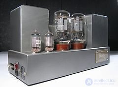
The ULF Quad II (1958) is an example of low-noise construction on shielded lamps. In the foreground on the left is the balanced input cascade on the EF86 pair [94] .
Pentodes of all types have a higher level of intra-tube noise than comparable characteristics of a triode in terms of power and steepness [95] . In addition to the "triode" noise, all screened lamps are characterized by current distribution noise (English partition noise ), surpassing shot noise by 1.5 ... 5 times. All "low-noise" pentodes are such only in comparison with conventional pentodes [96] [97] .
Inside the type of broadband pentodes, one can distinguish a circle of low-noise lamps intended for input stages of amplifying circuits (6D39G, 6Zh43P). They are characterized by high steepness (up to 30 mA / V in nominal mode) and stable distribution of currents between the anode and the shielding grid [98] .
The group of low-noise low-frequency pentodes is limited to the common EF86 lamp. (analogue - 6F32P [99] ), less well-known E80F, EF804, EF806, 5879 [100] and rare German lamps of the “postal” C3 family [note 12] . At low frequencies, the pentode noise is aggravated *** by the flickering noise of the cathode current and the humming noise induced by the heater in the cathode circuit. Therefore, for low-frequency low-noise lamps, the main thing is the quality of manufacture of the cathode and heater [101] , the mechanical stiffness of the intra-tube fittings and the overall culture of the assembly of the cathode-grid assembly [102] . In amplifiers of small signals, the minimum of noise is achieved with a certain combination of U C1 and U c2 , with a nominal or increased voltage of an incandescent [98] . In LF power amplifiers, it is not the lamp's own noise that is important, but a thorough design study. For example, the Quad II ULF (the first cascade is the EF86 pentodes, the second is the ray tetrodes KT66 (Eng.) Russian) was second only to the Williamson amplifier (Eng.) Rus. In signal-to-noise ratio. with the first cascade on the triode [94] . ClassicMullard 5-10 (English) Russian. with the same EF86, in contrast, has a high noise [103] .
The load resistance of the amplifier stage on the pentode R N , as a rule, is many times less than the internal resistance of the lamp R a ( R H R R a ). R H and R a form a voltage divider, through which the noise coming to the power supply circuits closes to ground. In HF amplifiers, this interference does not matter - it is effectively blocked by interstage separation capacitors. In LF amplifiers, network interference freely passes through interstage tanks or transformers. When capacitive coupling of the cascades to the input of the next cascade, most of the interference voltage is transmitted to the lower arm of the divider. In the case of transformer coupling, a smaller part of the interference voltage is transmitted to the next stage, which falls on the upper arm of the divider (on the primary winding of the transformer). Therefore, the use of transformer coupling in amplifiers on pentodes mitigates the requirements for filtering noise on the power supply circuits. In triode amplifiers, on the contrary, R H »R a , therefore the use of transformer coupling tightens the requirements for filtering [104] .
Pentodes are very sensitive to noise on a shielding grid, [105] so it usually feeds from a separate RC filter (even better from an LC filter) with a large time constant. You can do the opposite and apply a metered voltage of network interference to the screening grid, compensating for the influence of “normal” interference [106] . Required for this resistance in the circuit of the screen are chosen empirically. The exact calculation of the scheme in practice is not possible, since the manufacturers did not standardize and did not document the characteristics of the control on the shielding grid. Once compensated, the noise may return as the lamps age or when they are replaced [106] .
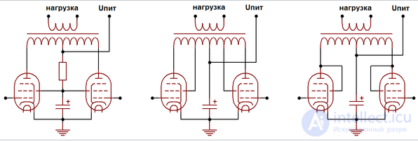
Normal (pentode), ultralinear and triode switching on of the pentode in a two-stroke power amplifier.
Power circuits are shown simply, the bias circuit is not shown.
When a screening grid is connected to the anode, the pentode degenerates into a two-anode triode with an almost constant current distribution between the screen and the anode. Since the current of the shielding grid in the triode inclusion completely passes through the load, the slope of such a “triode” is somewhat higher than the reference slope of the pentode [57] [note 13] .
Weber argues that the usual pentode in the triode inclusion should be compared not with the triode, but with the tetrode , since its antidynamic grid remains closed to the cathode. According to Weber, it is possible to speak about triode switching on only when not only the screening grid, but also the anti-dinatron grid is connected to the anode [107] . In practice, the influence of the antidinatron grid in the triode inclusion can be neglected. The mode of operation of the pentode in the triode inclusion is fully equivalent to the “real” triodes, with two features:
In 1951, David Huffler (English) Russian. and Harbert Keros (eng.) Russian. they proposed to connect the shielding grids of the output lamps of the LF amplifier [note 14] to the taps from the primary winding of the output transformer [111] . The current-voltage characteristics of a pentode in such an inclusion are a cross between a triode and a pentode. Khafler and Keros argued that it is possible to pick up a tap point at which the amplifier still maintains a high efficiency close to the tetrode one, but its output impedance already falls to values close to the triode [111] . Thanks to the feedback on the shielding grid, the ultralinear cascade is able to combine the best properties of both the triode and the shielded lamp [112] .
Ultralinear inclusion is most beneficial in class B, and has been used mainly in class B amplifiers [113] . In the USSR, the ultra-linear circuit was used in both push-pull amplifiers of classes B and AB (for example, in the Symphony radio stations and Dnepr-11 and Dnepr-12 tape recorders), and in A - class one -cycle amplifiers (VEF-Radio , “Riga-6”, “Rigondas” of single-cycle series, etc.) [114] .
For the successful implementation of ultralinear ULF, high-quality, broadband output transformers with particularly low leakage inductances between all windings are needed [112] . For example, in the 1951 Häfler-Keros scheme, a transformer with a bandwidth of 10 Hz - 100 kHz was used with an uneven frequency response of no more than ± 1 dB [111] .
The ultralinear cascade is also picky about filtering the DC voltage component on shielding grids. In a conventional ultralinear cascade, all the anode voltage ripples pass through the shielding grids (including voltage dips when the output power surges). In addition, the power supply U c2 = U a disadvantageously limits the possibilities of increasing the anode voltage [note 15] . Van der Wien proposed to connect screens not to taps from the primary (anode) windings, but to insulated windings connected to a separate power filter [115] , but this scheme did not find practical application.
↑ Show compact

Comments
To leave a comment
Radio tubes and ion devices
Terms: Radio tubes and ion devices