Lecture
Electrode triode , or simply triode , is an electronic lamp that allows an input signal to control the current in an electrical circuit. It has three electrodes: a thermionic cathode (direct or indirect heat), an anode and one control grid. Invented and patented in 1906 by the American Lee de Forest. Commonly used to amplify, generate, and convert electrical signals.
The name of the triode in 1950-70, during the formation of semiconductor electronics, was also used *** for transistors - according to the number of conclusions, often with clarification: a semiconductor triode, or with an indication of the material: ( germanium triode, silicon triode).
Triodes were the first devices that were used to amplify electrical signals at the beginning of the 20th century.
The nonlinearity of the current-voltage characteristic of the triode is proportional to the third degree of the magnitude of the anode current [1] , i.e. It has higher linearity than semiconductor transistors. Due to this, vacuum triodes introduce minimal linear distortions into the amplified signal.
In the course of further improvement of the triode, multigrid lamps were developed: a tetrode, a beam tetrode, a pentode, and others.
At present, vacuum triodes are almost completely superseded by semiconductor transistors. The exceptions are areas where signal conversion with a frequency of the order of hundreds of MHz - GHz of high power is required with a small number of active components, and dimensions and mass are not so critical, for example, in the output stages of radio transmitters. Powerful radio tubes have an efficiency comparable with powerful transistors; their reliability is also comparable, but the service life is much less. Low-power triodes have low efficiency, since a significant part of the power consumed by the cascade, sometimes more than half of the total lamp consumption, is spent on the glow.
Also, some of the high-quality acoustic amplifier equipment of the Hi-Fi and Hi-End classes is still being made on the base of the lamps, despite the fact that the nonlinear distortion coefficient fixed by the instruments in almost any modern transistor devices is many times smaller than that of the lamp ones. [ source not specified 289 days ] Despite the high cost, such equipment is very popular with musicians and audiophiles due to its so-called more "warm", "tube" sound, which is perceived by man as more natural and close to what it was when recording the original sound. A triode is a simple design lamp with a high gain, so it fits well into one of the principles of building alternative sound engineering - the principle of minimalism, that is, the ultimate simplicity of the equipment.
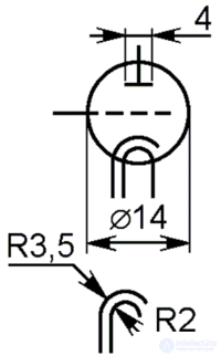
The triode can be made independently.

The scheme of the simplest vacuum triode with a direct-heated cathode
Circuit designation of a vacuum triode with an indirectly heated cathode
|
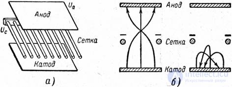
Imagine an electrovacuum device with a flat emitting cathode, a flat anode, and a third electrode — a wire grid (grid) placed between the cathode and the anode in a vacuum ( Figure 8-11 , a ). The voltage at the anode relative to the cathode is denoted by U a , and the voltage on the grid relative to the cathode is U c . The grid is introduced in order to make significant changes in the anode current I a using small voltage changes U c . In other words, the grid is designed to serve as an electrode that controls the anode current. |
||||
|
||||
|
A lamp with three electrodes is called a triode . It can be used for amplification and for generating cola *** s. Electrons moving from cathode to anode generally have the ability to fly between the grid bars. But the number of electrons passing through the grid in a second, significantly depends on the voltage on the grid. If it is negative with respect to the cathode, then the grid has a retarding effect on the movement of electrons, creating a repulsive barrier in their path. It is possible to set such a magnitude of the negative voltage on the grid, at which near the cathode the accelerating field of the anode will disappear, and with further increase of the negative grid voltage, the field near the cathode will become decelerating and the anode current will stop. In this case, it is said that a “locking” voltage is applied to the grid. If a positive voltage with respect to the cathode is connected to the grid, then in the space between the grid and the cathode the intensity of the accelerating field increases, and this leads to an increase in the anode current. Consequently, by changing the voltage on the grid, you can change the anode current from zero to the highest attainable value. In fig. 8-11 , b shows the trajectories of electrons emerging from the space charge zone perpendicular to the cathode surface, with a positive voltage at the anode and negative at the grid. The left figure corresponds to a small negative voltage on the grid (only two adjacent rods of the grid are shown here). The electrons, which start their motion in a straight line, are further deflected by the negatively infected grid rods and are deflected all the more, as the initial trajectory of the electron must pass to the rod. In a certain region behind the grid, the trajectories of electrons intersect, or, as they say, the electron flow is focused, and then goes by a diverging beam to the anode surface. The right figure corresponds to a significant negative voltage on the grid. The electrons cannot fly through the barrier created by the electric field of the grid and return to the cathode; no anode current. With a positive voltage on the grid, not only does the anode current increase, but some of the electrons moving from the cathode can be intercepted by the grid. Consequently, the current will exist not only in the anode circuit, but also in the grid circuit (grid current). Usually the grid current does not perform useful work. Real types of triodes have a grid in the form of a cylindrical spiral and the anode in the form of a round or flat cylinder. The physical processes in such triodes are similar to those described above; but in circular-cylindrical structures, the electric field and the trajectories of the electrons are directed along the radii of the cylinders. Dual triodes are widely used . Both triodes mounted in the same cylinder operate either in the same equipment cascade or perform different functions. Combinations of a dual diode triode in a common cylinder are also convenient for receivers. As was shown, the currents of the anode and grid circuits of the triode depend on the voltages on the anode and on the grid (assuming that the filament voltage is normal for a given lamp, providing the required emission of the cathode). A quantitative assessment of these dependences visually represents the characteristics of the triode. |
||||
|
||||
|
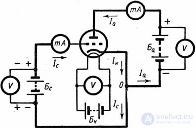
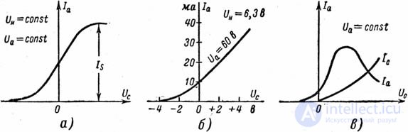
The main characteristic is the graph of the dependence of the magnitude of the anode current on the voltage on the grid at a constant voltage on the anode. This is the grid characteristic of the anode current (or, in short, the anode-grid characteristic). In fig. 8-12 shows the circuit of the anode and grid currents and the circuit of the filament of the triode. Milliammeters mA allow you to count the current of the anode circuit I a and the current of the grid circuit I with . Voltmeters V measure the anode and grid voltages and the filament voltage, respectively. In the cathode circuit, the current I c is obviously the arithmetic sum of the anode and grid currents ( I c = I a + I c ), which branch at common point 0 . Therefore, in the cathode circuit a separate instrument for measuring current is not required. For greater clarity, the anodic and grid circuits are shown by thick lines. Having established the normal filament voltage U n and the anode voltage U a specified in the lamp passport, we will change the voltage on the grid U c from negative values through zero and further in the range of positive values. Such an adjustment can in principle be carried out by rearranging the grid wire along the branches from the battery cells. It is practically more convenient to use a voltage divider (potentiometer), which is not shown in fig. 8-12 , to maintain the visibility of the scheme. At each value of the voltage on the grid, we will note the value of the anode current. With a significant negative voltage on the grid, the current I a is absent, since the electrons are repelled by the grid back to the cathode. By gradually reducing the negative grid voltage, we note that a current will appear in the anode circuit, which will initially increase slowly and then faster. This indicates the ability of a positive anode voltage to overcome the effect of a negative voltage on the grid, if the grid voltage has become much less than the anode voltage in absolute value. Reaching the zero voltage on the grid and changing the polarity of the grid battery B s , we will increase the grid voltage in the positive region. We will detect further increase in anode current. If the test lamp had a pure tungsten cathode, then with an increase in the positive grid voltage, the growth of the anode current would slow down, and then stop altogether. This would correspond to the saturation mode. The graph depicting the dependence obtained is called the grid characteristic of the anode current ( Fig. 8-13 , a ). The saturation current I s (at normal incandescence) characterizes the properties of a lamp with a tungsten cathode. However, the most important (working) section of the characteristic is its steep (almost straight) section. |
||||
|
||||
|
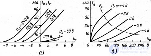
In a lamp with an activated (for example, oxide) cathode, the saturation current cannot be detected, since the emission current increases due to the additional heating of the activating coating by the anode current. Therefore, in its upper part, the characteristic is limited by the value of the anode current safe for the cathode. The approximate characteristic for a low-power triode with a heated cathode is given in fig. 8-13 , b . This characteristic, like the previous one, has a lower fold in the region of negative voltages on the grid. The second characteristic of the triode is a graph of the dependence of the magnitude of the grid current on the voltage on the grid at a constant anode voltage. As we know, the current in the grid circuit appears only at positive voltages on it, when part of the electron flow is "intercepted" by the grid wires. Naturally, the current directed towards the movement of electrons flows in the wires from the cathode to the grid, and in the lamp from the grid to the cathode (see. Fig. 8-12 ). For small positive grid voltages, the grid current is negligible — it is a fraction or unit percent of the anode current. But as the positive voltage on the grid increases, the number of electrons intercepted by it increases. Grid current becomes commensurate with the anode. With a relatively low anode voltage, a redistribution of the electron flux is possible, which leads to an increase in the grid current due to a decrease in the anode one if the positive voltage on the grid becomes higher than that on the anode. In fig. 8-13 , the current characteristic of the grid is shown together with the characteristic of the anode current at a low anode voltage and when the grid voltage varies within large limits. It should be noted that the removal of characteristics within such limits can lead to lamp deterioration, since with a large grid current, its conductors become very hot by electron bombardment. Once again we recall that in most cases the grid current does not perform positive tasks in hardware, and the power consumption for heating the grid is harmful. Now consider how the change in the anode voltage is reflected in the processes in the lamp and its characteristics. After removing the characteristics shown, for example, in Fig. 8-13 , b , we will increase the anode voltage and again remove the characteristic of the anode current on the grid voltage. With an increased voltage at the anode, the attractive force of electrons to it increases, and therefore the inhibitory effect of the negatively charged grid is overcome more successfully. Therefore, the characteristic of the anode current will start to the left, i.e. at a higher negative voltage on the grid, and all further values of the anode current will be higher than the previous ones with equal grid voltages. In fig. 8-14 , and shows the characteristics of the anode current on the grid voltage, taken at U a = 60 , 120 , 180 and 240 V. In the first approximation, all these characteristics differ only in location in the coordinate axes: with an equal step of the anode voltage, each successive characteristic is obtained (albeit approximately) as a result of the previous shift to the left by the same value. |
||||
|
||||
|
Here (below) shows the characteristics of the current grid, taken at anode voltage A group of characteristics taken at different DC voltages is called a family of characteristics . In fig. 8-14 , and the family of anode current characteristics (as well as the grid current characteristics family) of the grid voltage was given at constant anode voltages given each time. We emphasize once again that the main (steep) sections of the characteristics of the anode current are practically approaching straight lines, and the importance of this fact will be explained later. But the properties of the lamp can be studied on other types of characteristics, which are dependences of the anode current on the anode voltage with the grid voltage specified for each characteristic. Characteristics of this type are briefly called simply anodic . Returning to the diagram in fig. 8-12 and setting in it a constant voltage on the grid, equal to zero ( U c = 0 ), we will increase the anode voltage from zero to large positive values. We will remove the characteristic, both fundamentally and practically similar to the characteristic of the diode ( Figure 8-14 , b ). Indeed, at U a = 0, the current is zero, because the anode does not pull electrons. This means that the characteristic starts from the origin of coordinates and, having a lower curved section, goes on almost straightforwardly. If negative constant voltage is applied to the grid ( U с <0 ), then the characteristic of the anode current on the anode voltage will not start from the origin, but to the right; because in this case it is necessary to apply a positive voltage to the anode, sufficient to overcome the braking effect of the grid. The greater the negative grid voltage, the greater the shift of the characteristic to the right (see. Fig. 8-14 , b ). If a constant positive potential is set on the grid relative to the cathode, then the characteristic of the anode current is located to the left of the main one. The beginning of such characteristics also coincides with the origin of coordinates, but at the same time the initial part turns out to be convex. This sharp rise is due to the redistribution of electrons between the positive grid and the anode: at a very low anode voltage, electrons that fly through the grid fall into the retarding field between the grid and the anode and form a second volume charge between the grid and the anode. As the anode voltage increases, the anode current grows sharply due to the electrons of this space charge, which disappears, and also due to a sharp decrease in the grid current. In fig. 8-14 , b dot-dash defines the range of permissible modes of lamp use for heating the anode. This line connects the points corresponding to the permissible power of dispersion at the anode ( Pa = U a · I a ). For a lamp represented by its characteristics in the figure, the allowable power is only 2 watts . Instantaneous (pulse) power values can exceed this value, since the anode “cools” between pulses. The families of characteristics that we considered are called families of static characteristics, since they are removed at constant voltages on the electrodes. The family of characteristics gives a fairly complete picture of the properties of the triode. However, it is desirable to express these properties in numbers. Such quantitative expressions of the properties of the triode are its parameters . The triode is primarily intended to amplify signals. Усиление в триоде возможно благодаря тому, что сетка расположена между анодом и катодом и потому частично экранирует катод от прямого воздействия поля анода. Собственное же поле сетки воздействует на пространственный заряд беспрепятственно. Параметр, показывающий, во сколько раз сильнее изменение сеточного напряжения действует на величину анодного тока, чем такое же изменение анодного напряжения, называется коэффициентом усиления лампы и обозначается буквой Увеличив напряжение на сетке на |
||||
|
||||
|
при неизменном I a . Очевидно, что Иногда оказывается удобнее применять в качестве параметра величину, обратную коэффициенту усиления. Этот параметр называется проницаемостью и обозначается буквой D : |
||||
|
||||
|
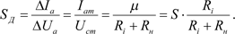
при неизменном I a . Физически проницаемость характеризует, какая часть силовых линий поля анода проникает сквозь сетку к катоду. Очевидно, что чем гуще сетка, тем меньше проницаемость, т.е. тем больше коэффициент усиления. Для разных применений триоды могут выбираться с коэффициентами усиления от нескольких единиц до сотни. В качестве параметра триода, характеризующего влияние сеточного напряжения на величину анодного тока при неизменном анодном напряжении, служит крутизна анодно-сеточной характеристики (или, как принято говорить, крутизна лампы). Величина крутизны показывает, на сколько возрастает анодный ток при увеличении напряжения на сетке на 1 В . Крутизна обозначается буквой S : |
||||
|
||||
|
при неизменном U a . Следовательно, по физическому смыслу крутизна имеет размерность проводимости. Но это - не проводимость какой-либо одной цепи лампы, а как бы "взаимная проводимость" цепей сетки и анода. Обычно для крутизны применяется исчисление в миллиамперах на вольт (а не в амперах на вольт), что оказывается удобнее практически. Пусть, например, прирост сеточного напряжения на 0,5 В вызвал увеличение анодного тока на 5 мА ; тогда крутизна составит 10мА/В . В триодах разных типов значения крутизны могут встретиться от 1-2 до 30-40 мА/В . Этот параметр также определяется конструкцией лампы: чем больше эмиттирующая поверхность катода и чем ближе к нему сетка, тем больше крутизна S . Разумеется, в качестве параметра триода (как и для диода) указывается крутизна на прямолинейном восходящем участке характеристики. Большая крутизна составляет достоинство лампы в большинстве применений. Можно изменять величину анодного тока также изменением напряжения на аноде при неизменном сеточном напряжении. Увеличив анодное напряжение на |
||||
|
||||
|
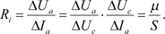
при неизменном U с . Внутреннее сопротивление выражается в омах, для чего в формуле (8-7) величины Удобно запомнить такое определение: внутреннее сопротивление, выраженное в килоомах, показывает, на сколько вольт потребовалось бы повысить анодное напряжение, чтобы увеличить анодный ток на 1 мА . Практически применяются триоды с величинами внутреннего сопротивления от 0,5 до 100кОм . Внутреннее сопротивление R i триода - не независимый параметр (так же, как и проницаемость D ). Если известны коэффициент усиления |
||||
|
||||
|
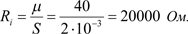
Пусть, например, лампа имеет крутизну S = 2 мА/В и коэффициент усиления |
||||
|
||||
|
Следовательно, триод имеет только два независимых параметра. Конструктивные изменения, влияющие на величину Указанную выше математическую зависимость между параметрами триода чаще дают в виде следующих формул: |
||||
|
||||
|
Конечно, эти соотношения справедливы лишь в том случае, если все параметры относятся к одному и тому же участку характеристик. Обычно их указывают для крутых (приближенно прямолинейных) участков. Если имеется экспериментально снятое семейство сеточных или же анодных характеристик анодного тока, то можно найти параметры триода для любого режима, охватываемого этим семейством. |
||||
|
||||
|
Возьмем семейство сеточных характеристик анодного тока ( рис. 8-15 , а ). Пусть требуется вычислить параметры для режима, определяемого приблизительно значениями U a Горизонтальный катет этого треугольника ( |
||||
|
||||
|
По мере перехода на нижние сгибы характеристик крутизна уменьшалась бы, а внутреннее сопротивление возрастало бы. Обычно в справочниках указывают параметры для режима, в котором рекомендуется эксплуатировать данную лампу. Остановимся кратко на определении параметров по семейству анодных характеристик ( рис.8-15 , б ). Здесь в характеристическом треугольнике горизонтальный катет Обратим внимание на то, что подъем анодной характеристики анодного тока определяет не крутизну, а внутреннее сопротивление лампы: чем положе эта характеристика (чем меньше В массовом производстве ламп определять параметры построением характеристического треугольника было бы слишком сложно. Однако методы автоматизированного измерения параметров основаны также на сопоставлении приростов напряжений и токов. Кроме основных (усилительных) параметров триода Поясним принцип усиления с помощью триода. Для того чтобы изменения анодного тока были пропорциональны изменениям напряжения на сетке (т.е. чтобы сигнал усиливался без нелинейных искажений, о которых упоминалось применительно к рис. 8-8 ), следует обеспечить работу лампы на прямолинейном участке сеточной характеристики анодного тока. Кроме того, в большинстве маломощных усилителей требуется обеспечить работу лампы без токов в цепи ее сетки. Наличие сеточного тока связано с бесполезным расходом мощности сигнала в цепи сетки, т.е. с уменьшением амплитуды его напряжения из-за падения этого напряжения на внутреннем сопротивлении источника сигнала. Чтобы работать без токов сетки, дополнительно включают в цепь сетки источник постоянного отрицательного напряжения U c0 , по величине превосходящего возможные амплитуды напряжения сигнала и называемого "напряжением сеточного смещения". |
||||
|
||||
|
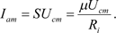
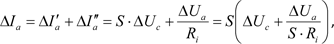
При выполнении указанных требований исходная точка m , определяющая режим лампы при отсутствии сигнала, находится на прямолинейном участке в левой области ( рис. 8-16 ). В этом исходном режиме в анодной цепи проходит постоянный ток I a0 . При воздействии переменного напряжения сигнала, имеющего амплитуду U cm , рабочая точка перемещается по характеристике между пунктами n и p ; значит, анодный ток пульсирует в пределах от i a.мин до i a.макс , т.е. в анодной цепи одновременно протекают переменная составляющая тока с амплитудой I am и прежняя постоянная составляющая I a0 . In fig. 8-16 сеточное напряжение и анодный ток развернуты во времени. Если параметры лампы известны, то можно выразить амплитуду анодного тока через амплитуду напряжения на сетке: |
||||
|
||||
|
In accordance with the last equality, we have the right to consider the action of alternating grid voltage as the inclusion of a generator of an emf. with amplitude In order to use the amplifying properties of a lamp, it is necessary to include a load resistance (for example, active) in its anode circuit, from which an amplified alternating voltage can be removed. The mode of operation of the lamp when acting on its input (on the grid-cathode terminals) of an alternating voltage and if there is a load resistance in the anode circuit can be called an operating mode. |
||||
|
||||
|
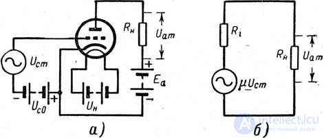
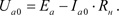
In the diagram in fig. 8-17 , and in the grid circuit of the lamp-amplifier, a source of a constant grid voltage U c0 and a source of alternating amplified voltage with amplitude U cm are connected in series. In the anode circuit in series with a source of constant supply voltage E a included load resistance R n . Anode current passes through this resistance; the constant component I a0 of this current forms a voltage drop I a0 · R n on the resistance R n , reducing the magnitude of the anode voltage applied to the lamp. A constant voltage remains at the terminals of the anode-cathode of the lamp. |
||||
|
||||
|
The operating mode of a lamp loaded with active resistance is characterized by the following circumstance: as the voltage on the grid increases, the voltage on the anode decreases (and vice versa). Indeed, when the grid voltage changes to |
||||
|
||||
|
||||
|
anode current and both voltages: |
||||
|
||||
|
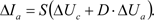
In the case of an amplifier as shown in fig. 8-17 , and an increase in the grid voltage causes an increase in the anode current, but this also increases the voltage drop across the load resistance, and the voltage at the anode decreases accordingly. As a result of these two opposite effects, the increase in the anode current will be less than it would be if there was no load resistance ( R n = 0 ), when there would be no reverse effect (reaction) from the anode. Let us now assume that an alternating voltage signal is acting on the input of a “loaded” lamp. The amplitude of this voltage, we will consider the change in the grid voltage, equating |
||||
|
||||
|
Transferring the terms containing I am to the left and putting I am beyond the brackets, we write: |
||||
|
||||
|
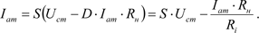
or, resorting to the expression of Ohm's law, we find: |
||||
|
||||
|
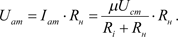
Thus, considering only the variable components of the voltages and currents in the anode circuit, we can compose an equivalent circuit for this circuit in accordance with fig. 8-17 , b . Here the amplifier is depicted as an emf variable generator. with amplitude How many times does the voltage increase in such a device? The voltage at the output of the amplifier, i.e. on the resistance R n (amplified voltage signal), |
||||
|
||||
|
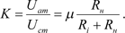
The ratio of the amplified AC voltage to the voltage of the signal acting on the grid is called the gain of our device (voltage gain) |
||||
|
||||
|
Therefore, the gain can be calculated by knowing the parameters of the lamp and the value of the load resistance. Let, for example, the lamp in the selected mode has In order to determine how abruptly the anode current of a loaded lamp changes with changes in the grid voltage, let us divide both parts by U cm in the formula (8-9) and call the ratio |
||||
|
||||
|
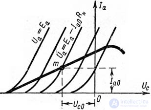
The steepness of the dynamic characteristic, therefore, is less than the steepness of the static characteristic of the same lamp, and, moreover, less, the greater the load resistance R n compared to R i . In fig. 8-18 shows a family of static characteristics. The initial mode is determined by the position of the point m on the characteristic that corresponds to the constant offset U c0 on the grid and the voltage on the anode U a0 = E a - I a0 · R n . |
||||
|
||||
|
With changes in the grid voltage on both sides of U c0, the anodic current varies according to the dynamic characteristic, the slope of which corresponds to the formula (8-11) and which is shown in fig. 8-18 thickened line. Note that the dynamic response starts on the left with the static one corresponding to U a = E a , where E a is the total voltage of the anode battery. On the right, in the area of positive grid voltages, the dynamic characteristic may have a decrease due to small residual voltages at the anode (see. Fig. 8-13 , c ). The construction performed in Fig. 8-18 , refers to a lamp loaded with an active resistance R n , the value of which we consider the same for both direct and alternating anode current. In cases where the load resistance contains reactivity, the construction of the dynamic characteristics may have certain features. |
||||
 .
. U с вольт, мы будем наблюдать прирост анодного тока. Если бы мы захотели восстановить прежнее значение тока, убавляя напряжение на аноде, то мы должны были бы уменьшить его на


 210 В и
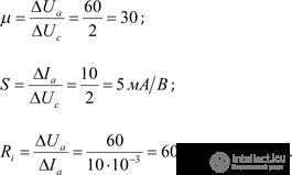
 ), тем больше R i .
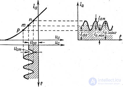


Comments
To leave a comment
Radio tubes and ion devices
Terms: Radio tubes and ion devices