Lecture
Triodes find their use in cascades of low-frequency amplification of receivers, in amplifiers of ultrahigh frequencies performed according to special schemes, in many pulsed devices and sometimes in powerful stages of transmitters. However, the triode is not the main type of lamp for radio equipment because of its inherent flaws. The first drawback of the triode is the significant capacity of the anode grid ( C ac ). This capacitance for triodes is in any case a few picofarads and, with signals of sufficiently high frequencies, gives noticeable conductivity. | ||||
| ||||
The second disadvantage of the triode is its small gain Both of these drawbacks are reduced to a certain extent by placing another electrode between the control grid and the anode, the shielding grid . Such an addition gives a four-electrode lamp - a tetrode . One of the possible structures of the tetrode and the scheme of its inclusion (with resistance in the anode circuit) are shown in Fig. 8-20 . The shielding grid, which covers the entire control grid and the cathode, is mounted on a horizontal flat metal disk. The shielding grid and disk weaken *** capacitive interaction between the anode and the first grid, as well as between their mounting wires. | ||||
| ||||
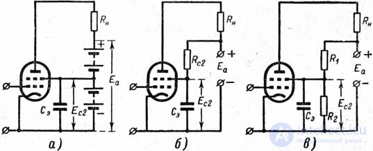
The C 2 grid in the tetrode reduces the capacitance between the anode and the control grid to a value on the order of hundredths and even thousandths of picofarad. Thus, the feedback between the output circuit and the input circuit (that is, the conductivity The shielding grid should not have zero potential relative to the cathode, since in this case it will not give the electrons the acceleration necessary for their movement towards the anode; the anode through two grids creates a weak attraction of electrons, and the current in its circuit will be too small. Therefore, a positive voltage from the source E c2 ( Fig. 8-20 , b ) is supplied to the shielding grid, and the magnitude of this voltage is usually taken from 0.25 to 0.5 anode voltage. Naturally, part of the electrons in this case will be intercepted by this grid and a current I c2 will arise in its circuit, and the cathode current I will turn out to be the sum of three currents. Useful current I c2 does not perform. In fig. 8-21 shows the possible options for powering the shielding grid from the anode battery: using a drain from the desired part of the battery, using series resistance, which quenches the excess part of the total battery voltage ( I c2 · R c2 ), and using a divider consisting of two resistances ( R 1 and R 2 ). The first method has practical inconveniences, the second is beneficial for battery-powered receivers, and the third, along with the second, is used for AC-powered receivers through a rectifier. | ||||
| ||||
Between the shielding grid and the cathode, the capacitor C e should be switched on, which creates an almost short circuit of this grid to the cathode for an alternating current signal frequency. The capacity of this capacitor for radio frequency signals is tens of thousands, or at least thousands of picofarads. This capacitor eliminates the reverse effect of the anode on the control grid through two successive capacitors (anode-shielding grid and shielding-control grid), diverting alternating current from the shielding grid to the cathode; it also ensures the constancy of the potential of the shielding grid relative to the cathode, excluding the effect of this grid on the variable electron flow. The second drawback of the triode (the "right" location of the characteristics with a large | ||||
| ||||
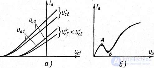
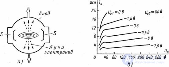
In fig. 8-22 , a shows two groups of characteristics corresponding to two values of the voltage U c2 , but with the same (for both groups) anode voltages. These groups are heavily offset from each other. In each group - two characteristics, taken at different values of U a . We see that the effect of the change in U a is insignificant; it leads only to a small "fan-shaped" discrepancy of characteristics. The small effect of U a changes corresponds to a large lamp gain. At the same time, with the right choice of U c2, the family of anode characteristics for the voltage of the control grid can be obtained sufficiently “left” for normal values of U a . A simple tetrode also has its disadvantage, preventing the wide application of this type of lamp. If during the operation of the amplifier the voltage at the anode is lower than on the shielding grid, then there is a sharp decrease in the anode current. This phenomenon is called the dinatron effect and is clearly observed on the anode current characteristic of the anode voltage ( Fig. 8-22 , b ): the characteristic receives a “dip” with two kinks. In some falling part of the AB of this characteristic, an increase in the anode voltage leads to a decrease in the anode current, which causes distortion of the amplified signal. The dinatron effect is based on secondary electron emission from the metal surface: when sufficiently fast electrons strike the metal surface, some of the energy is spent on heating the metal, but some of it is transferred directly to free electrons inside the metal, giving them the opportunity to go outside. This is the secondary emission of electrons. One fast electron can release several secondary electrons from a metal. Secondary emission may exist, for example, from the surface of the anode in the triode, but it is imperceptible here, since slow secondary electrons cannot move away from the anode and are attracted back to them (as many electrons are released, as many return and return). In the tetrode (see Fig. 8-22 , b ), as the anode voltage rises from zero, the anode current first increases, since at low speed the primary electrons cannot knock out the secondary ones. Further, with an anodic voltage increase, secondary emission occurs; the number of electrons knocked out is larger than the number of primary electrons, and the anode current decreases. The secondary electrons are attracted by the shielding grid, the potential of which is higher than the anode one, and the current in the shielding grid circuit increases. Further, as the anode voltage increases, a larger and larger fraction of secondary electrons returns to the anode; anode current increases. Moreover, at high voltages at the anode, the anode current additionally increases due to the attraction of secondary electrons knocked out of the shielding grid. How to eliminate the dinatron effect in the tetrode? One of the ways to this is the radial construction of the tetrode ( ray tetrode ). In such a tetrode, both its grids are made with the same number of turns, and the turns are placed strictly in the alignment (against each other). Due to this, electrons, acquiring the shape of flat rays after focusing with the first grid, fly through the second grid without hitting its coils. This reduces the useless current in the shielding grid circuit. The cylindrical shape of the anode of this lamp has a large radius, and its inner surface is removed from the flat sides of the shielding grid, as a result of which the attraction of secondary electrons to the shielding grid weakens. So that electrons exit only through the flat sides of the grid, i.e. along the longest path to the anode, vertical metal plates S connected to the cathode are placed in the lamp, i.e. having a zero potential. These plates repel electrons away from themselves, contributing to the formation of "rays" of the fan-shaped form ( Fig. 8-23 , a ). | ||||
| ||||
If in the radiation tetrode the voltage of the screening grid is higher than the anode one, then in the gap between the anode and the screening grid the primary electrons are decelerated and a negative space charge is formed. It repels secondary electrons knocked out of the anode, and returns them back to the anode. This means that the space charge plays a "protective" role. In a typical tetrode, the electron flow is scattered by the windings of the grids and cannot create a similar space charge. In fig. 8-23 , b shows the anode characteristics of the radiation tetrode. Due to the design described above, the dinatron "dips" are quite insignificant, the working sections are flat areas starting at low anode voltages. Radial tetrodes are used in the output stages of receivers and in transmitting devices, including a sufficiently large power. There is another way to eliminate the dinatron effect: on the path of the electrons between the shielding grid and the anode is placed a third grid, usually connected to the cathode, i.e. having a zero potential that prevents the movement of secondary electrons from the anode to the shielding grid. The third grid is called the protective or antidinatronic , and the lamp with five electrodes is called pentode . The advantages of the pentode — the low throughput capacity, the left arrangement of the grid characteristics of the anode current with a low anode voltage, and the elimination of the dinatron effect — provide the pentode with a very wide application. The scheme of the simplest amplifier on the pentode is shown in Fig. 8-24 . | ||||
| ||||
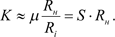
The presence of three grids makes the pentode gain very large. It turns out, therefore, that the internal resistance (about one million ohms ) is very large. The slope has values approximately in the same range as for the triode. In pentodes, the size of the passage capacitance of the same order as that of tetrodes, or even less. Large values of the internal resistance of the pentodes indicate that the increase in the anode voltage very little moves the grid characteristic of the anode current. However, when calculating the gain of a lamp loaded with resistance by formula (8-9), we can neglect in the denominator the value of R n compared to a very large value of R i . Then we get: | ||||
| ||||
To enhance the most important parameter of the pentode is the slope S. Of course, the gain of a loaded lamp is much less than its static gain ( It follows from the above that the steepness of the dynamic characteristic [see formula (8-11)] will practically not differ from the steepness of the static characteristic, and therefore it does not make sense to graphically depict the work of the loaded pentode as it was presented for the triode in Figure 8-18 (the inaccuracies will be too large). Much more precisely and more clearly the work of the loaded pentode is depicted in the family of anode current characteristics by anode voltage. | ||||
| ||||
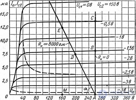
As an example in fig. 8-25 shows a family of anode characteristics of a widespread pentode of type 6Ж3П ( S = 5 mA / V , R i = 0.8 MΩ , We have already indicated that the working areas of the anode characteristics of the pentode are flat, almost straight sections; as you know, the greater the internal resistance R i , the more canopy the characteristic. The normal voltage of the anode power source is chosen so that the point A lies under the area of straight sections of characteristics. If the resistance R n = 0 (short-circuited anode circuit), then with an increase in the voltage of the first grid, the anode current would increase along the vertical straight line ABC , since the anode voltage would remain unchanged and equal to 0A . If there is an active resistance R n in the anode circuit, then in the absence of the anode current, the value 0A of the initial anode voltage will remain, since there is no voltage drop on R n . With increasing voltage on the control grid, the anode current will increase and in proportion to it the voltage drop on R n will increase. Voltage between anode and cathode | ||||
| ||||
accordingly, it will decrease, and therefore the operating point from point A will move along the inclined line to point D , then to point E and t, e. The greater the resistance R n , the more inclined will be the straight ADE , i.e. the smaller the angle | ||||
| ||||
Once again, it can sometimes be more convenient to depict the processes of lamp operation with this type of dynamic characteristic than in the grid-anode coordinate system. In many amplifiers of weak signals, it is desirable to obtain the possibility of a smooth adjustment of the gain factor K. From the formula (8-12) it is obvious that to reach such an opportunity is possible by smoothly changing the steepness S of that section of the characteristics of the anode current through the grid voltage, where the operating point is located. This is achieved by the device control grid with variable winding pitch. With such a grid, a negative bias voltage sufficient to block the electron flow through frequent turns turns out to be insufficient for rare turns, and the characteristic gets an elongated tail ( Figure 8-26 ), to which the operating point should be moved when receiving strong signals. Usually in receivers such movement is carried out automatically. | ||||
| ||||
The main directions of work on the improvement of receiver-amplifier lamps relate primarily to the pentodes, as the most widespread form of these lamps. Work is underway to increase the steepness S , to increase the strength (for example, vibration resistance) of pentodes, and to improve other indicators, including durability. Замена сеток, навитых в виде спирали, рамочными сетками из туго натянутых тончайших проволок позволила уменьшить расстояние между катодом и сеткой и тем самым повысить крутизну (например, до 30 мА/В в пентодах типа 6Ж23П ). Другой способ повышения крутизны - введение дополнительной (четвертой) сетки между катодом и управляющей сеткой. Такая катодная сетка получает относительно катода небольшое положительное напряжение, вследствие чего электронное облако перемещается ближе к управляющей (второй) сетке, это и приводит к увеличению крутизны. Естественно, что число ламп с большой крутизной в усилителе уменьшается (при одном и том же общем коэффициенте усиления) по сравнению с числом ламп, имеющих малую крутизну. Для переносной миниатюрной радиоаппаратуры созданы отечественные лампы со стержневыми электродами. В них центральное место (в вертикальной конструкции) занимает катод (нить прямого накала). Параллельно катоду по бокам размещены два стержня, выполняющие роль первой сетки. Электроны между этими двумя стержнями расходятся в обоих направлениях и на своем пути проходят мимо стержней, являющихся второй и третьей сетками и доходят до стержней, выполняющих роль анода. Стержни, прочно закрепленные внутри сверхминиатюрного баллона, обеспечивают лампе вибропрочность. Чтобы закончить параграф о лампах с многими электродами, следует упомянуть также о специальных видах приборов для преобразования частоты в супергетеродинных приемниках. Это лампы двойного управления электронным потоком; иначе говоря, на пути электронов от катода к аноду в них имеются по две управляющие сетки. На одну из управляющих сеток воздействует напряжение сигнала высокой частоты, а на другую - напряжение коле***ний собственного генератора (гетеродина). При таком совместном управлении электронным потоком в цепи анода может быть выделено коле***ние, частота которого равна разности частот сигнала и гетеродина. В этом и состоит процесс преобразования частоты, с описанием которого мы встретимся в следующих главах. Гетеродин требует для своего выполнения отдельной лампы (обычно триода). Но возможно размещение электродов лампы гетеродина и в одном баллоне с лампой двойного управления; именно о таких лампах мы и будем говорить. Лампа с семью электродами или гептод имеет пять сеток (она называлась прежде пентагридом - пятисеточной лампой). Первая и вторая от катода сетки вместе с катодом образуют триод, входящий в состав гетеродина. Третья сетка, получающая напряжение сигнала, тоже управляет электронным потоком. Четвертая сетка (соединенная с сеткой второй, т.е. с анодом триода) - экранирующая, пятая сетка - защитная. Для преобразования частоты применяют пентод и триод, объединенные в одном баллоне (триод-пентод). Встречаются также сочетание гептода с триодом и другие комбинированные лампы для преобразования частоты. | ||||
По мере развития радиотехники возрастало число различных типов электронных ламп. Для ряда специальных применений потребовались и специальные характеристики ламп, добиться которых можно было путем введения в лампу дополнительных электродов. Так появились многоэлектродные лампы.
Основным применением многоэлектродных ламп является преобразование частоты в супергетеродинных приемниках. Эти лампы имеют по две управляющие сетки, к которым подводятся два различных по частоте напряжения, под действием которых изменяется анодный ток (в супергетеродинном приемнике на одну управляющую сетку подается входное напряжение высокой частоты, а на другую сигнал местного генератора— гетеродина). Благодаря этому в анодной цепи таких ламп можно выделить напряжение, частота изменения которого равна разности частот, подведенных к обеим управляющим сеткам лампы (в супергетеродинных приемниках — напряжение промежуточной частоты). Остальные сетки в многосеточных лампах в зависимости от их назначения включаются по-разному.
К этому типу ламп относится гексод — шестиэлек- тродная лампа, имеющая четыре сетки. На первую сетку (считая от катода) подается напряжение местного гетеродина, на третью — сигнальную сетку — входной сигнал. Вторая и четвертая сетки являются экранирующими. Гексоды применялись в супергегеродинных приемниках для смешивания разных частот, поэтому их называли смесительными, или смесителями. Для преобразования частоты в супергетеродинном приемнике с гексодом требовались две лампы: смеситель и гетеродин, генерировавший вспомогательную частоту (для этого применялся триод). Желание уменьшить в приемниках количество ламп привело к созданию в одном баллоне смесителя и гетеродина. Такие многоэлектродные лампы получили название преобразовательных, или преобразователей. К их числу относятся:
— гептод (пентагрид)—семиэлектродная лампа с пятью сетками. Лампа состоит из двух частей: триод- ной, в которую входят катод и первая и вторая сетки (вторая сетка выполняет функцию анода), используемые в гетеродине и тетродной части; в тетродную часть, являющуюся смесителем, входят остальные электроды;
— октод — восьмиэлектродная лампа, являющаяся сочетанием триода и пентода. Так же как у пентода, триодная часть лампы используется как гетеродин, а лентодная как смеситель.
Схемы многоэлектродных ламп приведены на рис.50.
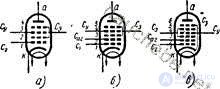
Fig. 50. Schematic representation of multigrid radio tubes: a - hexode; b - heptod (pentagrid) - converter; in - oktod; C y - control grid (signal); S e - grid zkraiuryyunhaya; C 3 - protective mesh; C ar - heterodyne anode grid; C g - sstka control heterodyne
 C ac between the chains of the anode and the grid ( Fig. 8-19 ). The harmful phenomenon of this capacitance lies in the fact that under the action of an alternating voltage formed on the anode in the presence of load resistance, an alternating current is branched from the anode circuit through this capacitor into the grid circuit. This means that the output voltage acts back on the input of the lamp, i.e. there is a so-called feedback. The combined effect on the input of a lamp of two voltages (signal and feedback) can drastically and not *** unfavorably change the amplifying properties of the lamp.
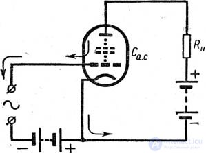
 . It would seem that the design of a sufficiently dense grid can achieve the gain of any desired value. However, in this case, a small negative voltage on the grid will lock the lamp, and therefore its characteristics (see. Fig. 8-14 , a ) will be located mostly to the right of the origin of coordinates - in the area of positive grid voltages. It is customary to say that a triode with a large
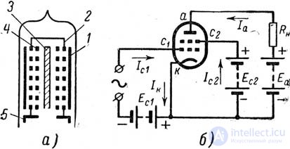

 ).
). 
 . This line is called the dynamic characteristic in the anode coordinate system. In the figure the slope


Comments
To leave a comment
Radio tubes and ion devices
Terms: Radio tubes and ion devices