Lecture
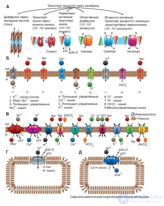
With all the diversity of the structure and physicochemical properties of molecules of penetrating substances, two mechanisms for the movement of substances through the membrane can be distinguished - by simple diffusion, i.e. without the help of a specific carrier, and with the help of specific carriers. In the first case, diffusion of the compounds is emitted directly through the lipid bilayer of the membrane (Fig. 1-7 A) and ions through the ion channels (Fig. 1-7 B). In the second case, the so-called facilitated diffusion, primary active transport and, finally, secondary active transport are distinguished.
We first consider simple diffusion. Through simple diffusion without the help of a special carrier, firstly, the transport of the compounds is carried out directly through the lipid bilayer. In this case, the penetration of substances into the cell proceeds by dissolving them in the lipids of the cell membrane, therefore this method is inherent in water-insoluble organic compounds and gases (for example, oxygen and carbon dioxide). Secondly, substances move through the ion channels of the cell membrane, connecting the cytoplasm of cells with the external environment. The ion channel is a protein structure based on the membrane α-subunit, formed by domains and looks like a donut with a hole in the middle — sometimes, through which the ions move. Cells use this path for the transport of predominantly Na +, Ca 2 +, K + ions (Fig. 1-7 B). This is a passive ion transport, which is determined by gradients of concentration and electric field (electrochemical gradient).
In this case, the concept of "gradient" differs from its definition in mathematics or physics. In physicochemical or biological systems, the term “gradient” is used when it comes to movement from a larger electrochemical
potential to a smaller one, and when moving from a smaller electrochemical potential to a larger one, the term “against the gradient” is used.
The change in the electrochemical potential Δμ (without taking into account chemical energy, or chemical potentials) can be written as:

This is the maximum work that can be done when transferring one mole of ions. In this case, RTln (C 2 / C 1 ) is equal to the work on concentrating the solution from C 1 to C 2 , and zF (φ 2 -φ 1 ) is equal to the work on overcoming the electric repulsive forces arising from the potential difference (φ 2 -φ 1 a) between solutions.
With the help of specific carriers, an energy-independent facilitated diffusion of a number of compounds is carried out (Fig. 1-7 C, D and D).
Energetically dependent primary active transport of ions Na +, Ca 2 +, K + and H + is the transfer of substances against their electrochemical gradients with the energy of ATP. As a result of the active transfer of ions, cells are able to accumulate them in higher concentrations than the environment, and in spite of their charge. Many gradients that occur on the cell membrane and serve as a necessary condition for the passive transfer of ions through ion channels appear precisely as a result of their active transport. Thus, K + and Na + concentration gradients result from the active transfer of these ions, i.e. work special Na + / K + -pump. Due to the difference in concentrations created on both sides of the membrane, these ions are diffused along gradients and the potential of the membrane is generated.
Finally, the secondary active transport of a number of ions and molecules also uses energy accumulated due to the consumption of ATP and spent on creating a concentration gradient (which gives the name to the mode of transport).
Fig. 1-7. The basic principles of the transport of ions and certain substances through the membrane and some transport systems in the cell membrane and the membrane of organelles.
And - the main ways of transport of substances through a membrane are shown. B - various types of ion channels are shown, providing ion transport along an electrochemical gradient. B - pumps, providing transport of ions against the concentration gradient, exchangers and conveyors. G and D - organelles transport systems
First of all, we consider a model of molecular organization of a potential-controlled Na + channel.
The Na + channel consists of a widely branched α-subunit, the molecular weight of which is approximately 260 kDa (Figure 1-8 A). The branched α-subunit is associated with additional β-subunits (Fig. 1-8 B). Na + channels in the cells of the central nervous system of adult animals contain β 1 - (or β 3 -) and β 2 subunits, while Na + channels in skeletal muscles in adult animals have only β 1 , a subunit. The pore-forming α-subunit is sufficient to ensure the function, but the kinetics and potential dependence of the portal channel mechanism is modified by β-subunits. In the Na + channel, the α-subunit is organized into 4 homologous domains (I-IV), each of which contains 6 transmembrane α-helices (S1-S6 segments), and the additional loop of the pore is located between the S5 and S6 segments. A loop outside limits the narrow entrance to the pore, while the S5 and S6 segments restrict the inner, wider exit from the pore. S4 segments in each domain contain positively charged amino acid residues in every third position, acting as gate charges and moving through the membrane to initiate channel activity in response to membrane depolarization. Short intracellular
a loop connecting homologous domains III and IV, acting as an inactivation gate, forms a fold, penetrating into the channel structure and blocking the pore from the inside during long-term depolarization of the membrane.
In recent years, a new standard classification has been developed for Na + channels (Fig. 1-8 B), based on the similarity between the amino acid sequences of the channels. In this classification, the individual channel is represented as a chemical symbol, which shows the main ion passing (Na) with the main physiological channel regulator (potential - “voltage gate chanels”), and this is recorded together as Na V. The number after these characters shows the gene subfamily (currently it is only Na V 1.), and the number following the dot shows a specific channel isoform (for example, Na V 1.1). This last number was proposed in order to show the order in which each gene was identified. The overlapping variants of each member of the family are indicated by small letters following the number (for example, Na V 1.1a).
The nine mammalian Na + isoforms that have been identified are functionally more than 50% identical in their amino acid sequence in transmembrane and extracellular domains, where the amino acid sequence is the same. This is enough for a clear alignment of all Na + channels.
Fig. 1-8. Planometric model of molecular organization of a potential-controlled Na + channel.
And - pore-forming α-subunit. The main structures of the α-subunit are shown as transmembrane cylinders, representing α-helical segments. The bold lines show polypeptide chains of each subunit with a length approximately proportional to the number of amino acid residues. The α-Subunit consists of four domains (DI-DIV), each of which consists of six segments (S1-S6). The S4 segment is a putative voltage sensor. B - the complete channel structure, including the α-subunit and β 1 -, β 2 subunits. The extracellular portions of β 1 -, β 2 subunits are shown as folds. Ψ - areas of likely glycosylation; P - phosphorylation sites for protein kinase A (circles) and protein kinase C (diamonds); h is the inactivation particle in the loop of the inactivation gate. B - similarity of amino acid sequence and phylogenetic relationship of α-subunits of potential-controlled Na + channels. A comparison of amino acid identity for the Na + channels of Na V 1.1-Na V 1.9 is shown. Given the gene number and chromosome number in humans
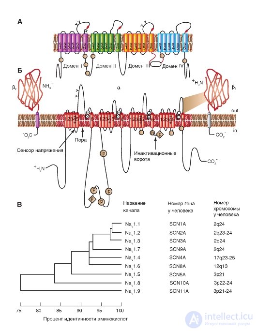
The pore diameter of the Na + channel is very small. It is only slightly larger than the diameter of the ions that pass through these channels, which prevents large polar organic molecules from entering them.
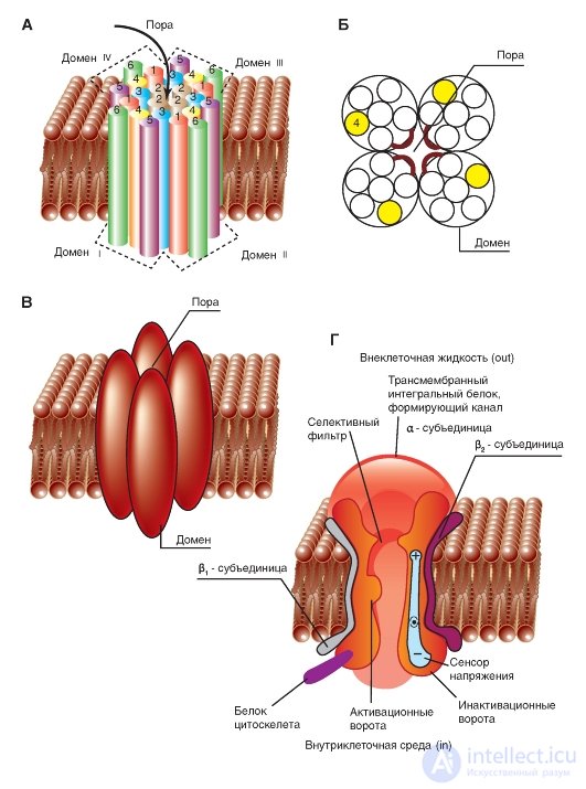
A three-dimensional image of the packaging of the four domains of the pore-forming α-subunit of the potential-controlled Na + channel, each of which contains 6 numbered transmembrane segments (S1-S6), is shown in Fig. 1-9 A. It is time itself represented by a hollow cylindrical hole in the center of the package. Connections between segments are not shown. The planometric image of the cutoff channel is shown in Fig. 1-9 B. In this case, the three-dimensional image of the packing of the four pore-forming domains
The common α-subunit of a potential-controlled Na + channel can be represented as shown in Fig. 1-9 V.
In fig. 1–9 G channel is represented as a transmembrane macromolecule with a hole passing through the center. The ion channel includes several important structures, including the mouth of the channel, facing the side from where the ion enters (in this case the outer side of the membrane), the selective filter that evaluates the ion, activation and inactivation gate, which can block the channel for passage of ions, and finally, a voltage sensor that controls the operation of the channel. (Although for many ion channels a larger number of channel gates is shown, we will discuss their operation only from the standpoint of activation and inactivation gates.)
Fig. 1-9. Volumetric model of molecular organization of a potential- controlled Na + channel.
A is the structure of all four domains. In the diagram, the six transmembrane segments of each domain are represented as cylinders and are schematically combined together, as is customary. The links between segments and domains are not shown. One ion channel domain constructed by an integral membrane protein containing six transmembrane segments (S1, S2, S3, S4, S5 and S6), each of which has an α-helical configuration within the membrane. B - cross section of the ion channel, each of the four domains of which has six transmembrane segments. B - model of three-dimensional image of four domains with a pore in the middle. G - physiological model of a potential-controlled Na + channel
The simplest and widely known scheme of the operation of a potential-controlled Na + channel is shown in Fig. 1-10 A. The channel is a transmembrane protein located in the lipid bilayer of the membrane, attached to other membrane proteins or elements of the intracellular cytoskeleton. When the channel opens, a water pore is formed that passes through the membrane. The mouth of the pore is much wider than the size of the ion, only in a small area in the selective filter area does it taper to an atomic size, where the nature of the ion is determined. Hydrophilic amino acids form the pore wall, and hydrophobic amino acids are bound to the lipid bilayer.
At present, the mechanism of the canal gate has been studied sufficiently. One of his first tried to describe B. Hill. According to his point of view, based on the experiments of A. Hodgkin and A. Huxley and his own work, in response to the action of an electrical stimulus, that is, a change in the transmembrane potential, the protein conformation of the potential-controlled channel changes. These conformational changes are regulated by the electric field inside the membrane, are stochastic in nature and occur in a period from 30 μs to 10 ms. It is important that the opening and closing of the channel does not require high-energy chemical compounds. Channels open at one and closed at other transmembrane potentials. It was assumed that the electric field acts on the voltage sensor, which determines the transmembrane potential. Then the voltage sensor must transmit this information to the channel molecule itself for its conformational adjustment and a corresponding change in the frequency of opening and closing the channel.
In 1992, B. Hille suggested that conformational changes occur as a result of the general
redistribution of charge in the macromolecule that forms the channel, and are expressed in the form of opening or closing the gate of the channel (Fig. 1-10 A). In other words, the ability to open and close a channel's gate is controlled by a voltage sensor. In the case of a potential-controlled channel, the sensor should include many charged groups that move under the action of an electric field. It should be noted that the operation of the voltage sensor and the gate channel, shown in Fig. 1-10 A, was a working hypothesis B. Hille, expressed on the basis of an electrophysiological study of the channel conductivity.
Considering the channel from the standpoint of the presence of only two - activation and inactivation - gate, one can imagine the following sequence of events (Fig. 1-10 B). In response to membrane depolarization, changes in the channel molecule conformation occur: at the same time, the activation and inactivation gates begin to shift, but with different speeds and in different directions: the activation gates tend to open the channel, and the inactivation gates - to close. The rate of displacement of particles forming the activation gate is greater, and this leads to the opening of the channel (transition from the state of rest to the state of activation). At this time, sodium ions pass through the channel. The following change in transmembrane potential leads to the closure of the inactivation gate. This translates the channel from the activated state to the inactivated state.
When the channel opens, the ion current appears immediately, and when it closes, the ion flow also immediately stops. At the level of a single channel, the gate transitions are stochastic; they can only be described in terms of probabilities.
The potential-controlled Na + channel can be in three states: a state of rest, activation, and inactivation, which are presented as a model in Fig. 1-10 B.
Fig. 1-10. The operation scheme of the potential-controlled Na + channel.
A - the channel is a transmembrane macromolecule with a hole passing through the center. The functional areas of the ion channel — the selective filter, the gate, and the voltage sensor — were detected during electrophysiological experiments. B - model of the work of a potential-controlled Na + channel with activation (or m-gates) and inactivation (or h-gates). At rest, the channel is closed due to the closing of the activation gate. The displacement of the membrane potential in the positive region (up to the threshold value) causes the opening of the activation gate. When the maximum potential for a particular cell is reached, the channel is inactivated, i.e. inactivation gate closes


Comments
To leave a comment
Human physiology, hygiene and age physiology
Terms: Human physiology, hygiene and age physiology