Lecture
To read information from a compact disk, a laser head (LG) is used. A laser diode, an internal optical system (diffraction grating, cylindrical, collimator and other lenses, prism), focusing and tracking coils with a focusing lens, and a laser diode (Fig. 1.1) are installed in the LH package.
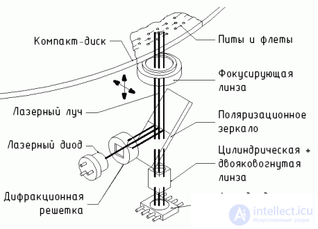 |
When the supply voltage is applied, the semiconductor laser diode generates a coherent (the phase difference of the waves is constant in time) a beam, which is divided by a diffraction grating into a main beam and two additional ones. After passing through the elements of the optical system and the focusing lens, these rays fall on a compact disc (Fig. 1.2).
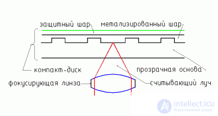 |
Accurate focusing of the rays on the disk is performed by the focusing coils, which establish the desired position of the lens. Reflected from the disk, the rays again fall on the focusing lens and further into the optical system. In this case, the reflected rays are separated from the incident due to their different polarization. Before reaching the photosensors (photodiode array), the main beam passes through a cylindrical lens, which uses the distortion effect to determine the accuracy of focusing (Fig. 1.3).
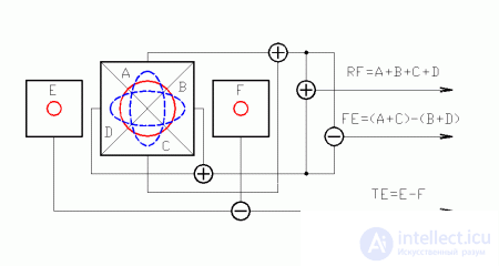 |
If the beam is focused precisely on the surface of the compact disk, the reflected beam on the photosensors has the shape of a circle, if in front of or behind the surface it has the shape of an ellipse.
The signals from the photosensors are preamplified, and the focus error (FE Error) is determined from the difference in the signals (A + C) and (B + D). With precise focusing, the FE signal is zero.
Two side beams fall on sensors E and F. They are used to track the passage of the main beam along the readable track (track) (Fig. 1.4).
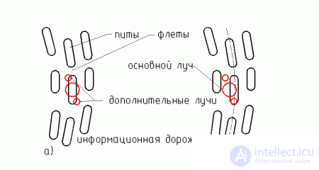 |
The difference between the signals E and F determines the tracking error (track tracking) TE (Tracking Error).
The sum signal from sensors A, B, C, and D is a high frequency (RF) signal (> 4 MHz) in EFM (Eight-to-Fourteen Modulation) format. It contains encoded audio information and additional data.
When a CD is inserted, the positioning motor (Slide motor) moves the laser head to the initial position until the "Initial head position" closes. (In some models for moving the carriage and positioning there is not two, but one engine.) Then the head begins to slowly move off until the limit switch opens.
The signal LDON servo circuit automatic power supply of the laser (ALPC - Automatic Laser Power Control) supplies power to the laser diode. Sometimes additional limit switches can be used to block the switching on of the laser and prevent the laser beam from getting into the eyes when the mechanism is disassembled, and sometimes the laser is always on with the carriage closed. The ALPC system maintains the power level of the laser diode at a given level. The current radiation power is controlled by a photodetector placed in the same housing with a laser diode.
The servo processor starts generating initial focus search pulses (FSR), which go to the focus servo circuits and then through the driver to the focusing lens. The focusing servo circuit is designed to compensate for the beating of a CD (up and down). The driver (output stage) is used to increase the power of the signals. The lens begins to move up and down. With accurate focusing of the beam on the CD surface, the focus error signal FE = (A + C) - (B + D) will be minimal, the FSR pulses will be turned off, and the focus servo circuit will begin to control the focus coil using the FEM signal, which is the corrected signal FE. After successful focusing, the FOK (FocusOk) signal is generated. If after 3-4 FSR pulses the FOK signal is not produced, the absence of a compact disc is detected and the player stops working.
The FOK signal is fed to the servo control circuits of the engine speed (ATMS). They generate MON (resolution), MDS (revolutions), MDP (phase), CLV (control) signals to control the engine and regulate its rotational speed. The engine starts to spin and pick up speed. In some players, engine start pulses are generated before the FOK signal is given along with FSR pulses. At a constant angular velocity of rotation from the beginning to the end of the disk, the diameter of the track and the linear velocity increase. The ATMS maintains a linear speed of rotation of the disk at a constant level, and after stopping the player, it slows down the engine speed.
The nominal data rate of the read information from the disk is 4.3218 Mbit / s.
At the same time, the FOK signal goes to the tracking servo circuit and activates its operation. This servo circuit provides accurate ray tracing in the center of the track. To track the position of the beam, a tracking error signal is used (TE = EF). The filtered high-frequency component of the signal TE (TER signal) is fed to the tracking coil. The tracking coil moves the lens in a direction perpendicular to the tracks and can read up to 20 tracks without moving the LH. The filtered low-frequency component of the signal TE (RAD signal) is fed to the positioning motor, which moves the LH across the disk field. The laser head periodically moves when the number of tracks read exceeds the limits for the tracking coil.
Tracking schemes can not independently determine the location of the beam on the information track or between them. For this purpose, a mirror detector is used, which, by the amplitude of the high-frequency EFM signal, determines the position of the beam and corrects it. If the beam is between tracks, then the amplitude of the EFM signal is minimal. With successful tracking, the tracking servo circuit produces a TOK (Tracking OK) signal.
After this begins reading the information from the disk. Pulsed by a pulse from a crystal oscillator, the PLL detector adjusts in frequency and phase to the high-frequency EFM signal and extracts data from it. In the shift register, serial data is converted to parallel. Further information is decoded, undergoes initial processing (deinterleaving, error correction, etc.) and is placed in the "half state" buffer. The ADMS maintains a buffer level of 50%. If the rotation speed is low and the buffer is less than 50% full, then the servo circuit will increase the engine speed and vice versa. You can slow down the disk for a while, but the sound will not stop. This is due to the presence of a buffer. A similar principle of work in AntiShock-schemes, but they have a larger capacity and percentage of filling.
The information in the buffer is written and read by the pulses WFCK and RFCK, respectively. The read information is divided into audio data and subcode. Subcode is service information that contains sync bits, information about the current track, time. The subcode uses servo circuits to position the laser head at the desired point. The subcode speed is 58.8 kbps. Audio data is processed in audio circuits, and an analog audio signal is output.
The conversion of sound from digital to analog format occurs in sound circuits. Initially, the data of the left and right channels are mixed (multiplexed) and placed in one stream. Audio data is further processed (interpolation, substitution) in digital audio circuits.
To improve sound quality and reduce noise, digital filters and accelerated sampling schemes (OVERSAMPLING) can be used. Digital filters convert the bit depth of the audio signal from 16 to 18 or 20 bits, reducing the quantization step in the output signal. When using an 18-bit filter and a DAC, the step is reduced 4 times and, accordingly, the sound becomes more pleasant. Accelerated sampling patterns move quantization noise (> 22 kHz) to higher frequencies. Data for a DAC is read and converted at a rate of 2, 4, 8, or 16 times greater than the nominal.
D / A converts digital signals to analog. Two options are possible (Fig. 1.5).
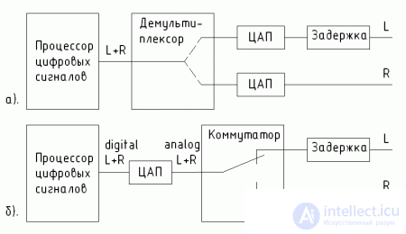 |
In expensive models the variant shown in fig. 1.5, and. The multiplexed digital signal is fed to a demultiplexer, which, by clocking pulses, divides it into 2 digital streams for the left and right channels, respectively. For each channel uses its own DAC. In another version (Fig. 1.5, b), one DAC is used, the analog signal from which is divided by the switch into two channels. In both cases, the delay line is used for time alignment of the data of the right and left channels.
The audio signals from the DAC output are amplified and fed to the output filters. Filters cut off the high-frequency components (> 20 kHz), quantizing noises and smooth the step.
The audio circuitry uses transistor switches, which are controlled by the MUTE signal and short the output signal to the case. If the disc is read normally, the processor in the "Playback" or "Rewind on track" modes disables the sound blocking. In all other modes, the MUTE function is activated.
The quality of the filter is directly dependent on the quality of the audio signal. In expensive models use filters of higher orders.

Comments
To leave a comment
Electromechanical devices of electronic devices
Terms: Electromechanical devices of electronic devices