Lecture
The digital system can be represented as a device for processing information, consisting of two parts: the operating room and the manager (Fig. 3.1).
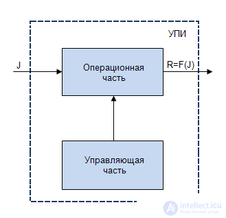
The operating part in this case is a set of functional units such as a counter, register, adder, decoder, etc., with appropriate links. On the basis of these functional units, all elementary operations are performed from the set determined by the type of dependence  (pic.3.1)
In most cases, these are operations of transfer, shift, memorization of numbers, analysis of signs accompanying the indicated operations. In practice, the set of operations varies depending on the specific technical requirements (the time to solve the problem, the type of system of elements), but in all cases it should be sufficient to solve the problem.
The solution process consists in the orderly (software) execution of the above elementary operations and for its technical implementation requires the use of a special sensor software distributed in time and space of a sequence of pulses. These pulses, acting on the corresponding nodes of the operating part, will provide an ordered sequence of elementary operations (Fig. 3.2). The operating part can be called an operation machine (OA).

Thus, the previously selected control part of the information conversion device can be considered as a unit that provides programmatic control of the information conversion process, that is, as a control machine (UA). The very principle of program management is reduced to an orderly (software) generation of signal-commands, the implementation of which leads to the achievement of a given goal.
The main element of the program control at the considered level is the microinstruction.
 - many microinstructions
  firmware automata as part of control devices.
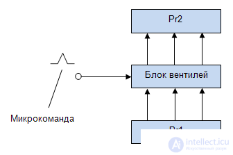
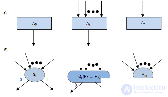
In the following, we will call the control signal (potential, impulse) a microcommand that performs one elementary step in the process of solving a problem (Fig.3.3).
Micro-operation - the name of a micro-command.
The micro-command presented in Fig. 3.3 corresponds to the micro-operation: “Transfer the number from Pr I to Prg2”.
In each management process, you can select a number of different micro-operations, which is called a set of micro-operations.
 -mikroomando consisting of micro-operations (MO)
The firmware is an ordered sequence of micro-operations of a given set. This definition is private, because covers only those cases of control when the sequence of control signals does not change depending on some signs accompanying the information processing. In the general case, the sequence of micro-operations may vary depending on the signs accompanying the information processing. Therefore, in addition to micro-operations, microprograms also introduce conditions, depending on the execution or non-fulfillment of which the sequence of micro-operations changes. On the basis of the absence or presence of conditions, depending on which the sequence of micro-operations changes, all the microprograms are divided into two groups: non-forked and forked. The branching firmware is divided, in turn, into two groups: microprograms without cycles and microprograms with cycles. In general, microprograms can contain as their parts all three types: non-branching, branching and cyclic.
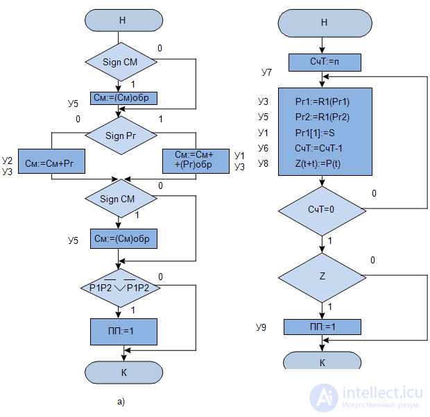
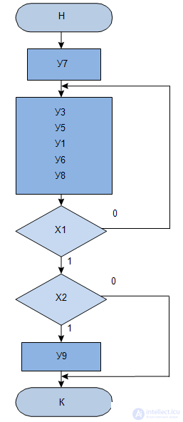
For example, in Fig.3.4) the MP operation of addition is shown. If we introduce a formal re-designation of micro-commands (  or
or  ), then for MP in Fig.3.4, b we get the GSA GSA MP shown in Fig.3.5.
The sequence of the MC is determined by the transition functions
 from a set of logical variables
  . The transition functions have two properties: completeness and orthogonality.

T


The orthogonality property says about the uniqueness of the transition, and the completeness property that this transition necessarily exists.
Methods of formal record of MP, satisfying the above properties, it is:
GSA are widely used in the practice of designing devices for digital computers and, in particular, firmware automata due to their good visibility, the simplicity of the language design and the possibility of transformations and the formal transition to automatic display.
The main characters used to write graph-scheme algorithms (GSA), we assume:
Of the entire set of operators stand out:
 ,
,  ,
,  .
. The initial operator in the future (if this is not specifically mentioned) will be considered as an operator, symbolizing the beginning of the algorithm.
Operator Record Feature in the GSA is that this operator does not include a single arrow.
The final operator will be considered as an operator, symbolizing the end of the algorithm.
Feature recording operator and in GSA is that not a single arrow comes out of this operator.
Arbitrary operators will be considered as symbols denoting certain actions, acts associated with the implementation of the algorithm.
Feature recording operators  consists in the fact that several arrows can be included in these operators, but only one arrow always comes out.
Under the logical condition we will understand the logical function of the form  where
where  elementary logical conditions. The peculiarity of recording logical conditions is that they can have several incoming arrows and only two outgoing ones marked with the symbols “O” and “I” in accordance with the value of the logical condition. In the future, we will also allow GSA to replace the left side of the expression
  its right side.
The arrows ensure the ordering of the sequence of statement execution and verification of logical conditions, as well as their interrelationships.
Algorithm execution always starts with an operator. and ends with an operator .
In general, for each operator vertex, the transition formula is written as:

and the properties of orthogonality and completeness are also respected. In addition, it is considered that the values of the sets of logical conditions do not change during the execution of statements.
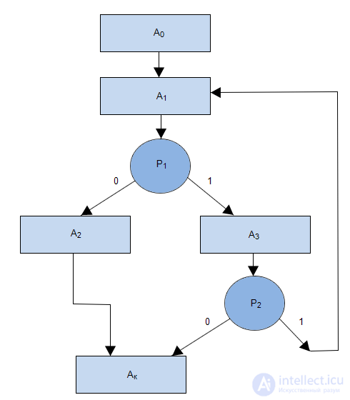
For MP, presented in Figure 3.7, the transition formulas will be written as:
 ;
;
 ;
;
 ;
;
 ;
;
They say that the matrix scheme of the algorithm (ISA) is specified, if a matrix of the form
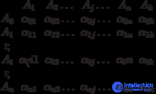
Where  operators,
 - initial and final operators,
 - logical conditions that have the same meaning as in GSA.
| A1 | A2 | A3 | Ak | |
|---|---|---|---|---|
| A0 | one | |||
| A1 | p1 | p1 | ||
| A2 | one | |||
| A3 | p2 | p2 |
In MCA  it is accepted to consider as such a logical function that if an operator was executed and on the resulting set
  values of elementary logical conditions function
  received a value equal to one, immediately after the operator the statement must be executed
  .
.
In Figure 3.1, a is given the ISA MP, shown in Figure 3.7.
The main advantage of the logic schemes of algorithms (LSA) considered below is that, being essentially a type of the language of operator schemes, they allow the algorithm to be written to a line, which is often convenient because it is possible to exclude the process of drawing, drawing, as is the case in GSA. The presence of a developed system of LSA transformations and the possibility of a formal transition to an automaton mapping are also important.
The main elements of LSA are, as in GSA, operators and logical conditions.
The main differences from GSA are that the upper and lower arrows are used to indicate the relationships between operators and logical conditions.
The logical scheme of the algorithm is a string composed of operator characters.  , or
, or  and logical conditions
  , as well as upper and lower arrows. Sometimes the upper and lower arrows replace the right and left half-boxes.
So, LSA is a line made up of operator characters. logical conditions  and upper
  and lower
  shooter, and:
 and one final
  ;
;  and ends ; with the same numbers; must have at least one top;
 Transition by logical condition  standing in LSA

done like this:
 then after
  will be fulfilled
  ,
,  then after will be fulfilled
  .
. Unconditional transition for clarity may be indicated by an additional symbol, for example  .
.
LSA for MP presented in fig. 3.7 looks like this:

The rule of reading LSA is as follows.
First, the element LSA is analyzed, immediately following the operator . If the considered element is an operator, then it is marked (written out) and in the next step, the right element (operator or logical condition) is analyzed.
If the element in question is a logical condition  this condition is checked;
Analysis of the LSA with the observance of the formulated rules leads after a certain number of steps to obtain a line of operators, called the LSA value for a given sequence of sets of logical conditions.
Let the LSA be given.

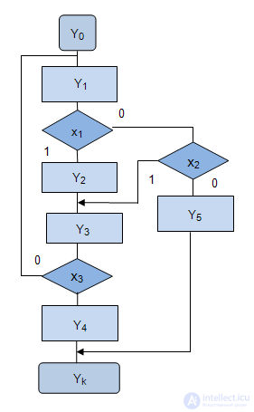
Construct the corresponding GAW. For the initial operator operator follows  further logical condition
  . If the logical condition is satisfied, that is
  , then the next statement is executed
  . If the logical condition is not met, that is
  , the next statement is executed
  , that is, the operator behind the bottom arrow with the number 1.
Next in LSA for the operator operator costs  and
and  . In such a sequence and depict them on the GSA. Next, we build in the same way.
One important feature of LSA is the possibility of ambiguous recording of the same algorithm.
Thus, the GSA in Figure 3.8 can be described with several more variants of the LSA:


Comments
To leave a comment
Theory of Automata
Terms: Theory of Automata