Lecture
The memory of the structural automaton is intended for storing the states of the automaton (Fig. 6.1).
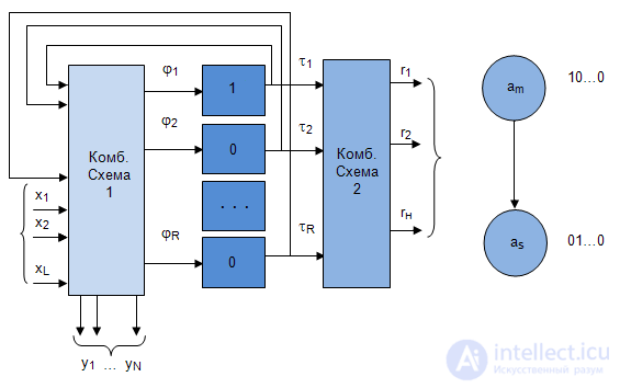
The number of memory elements is calculated by the formula  where M is the number of states of the abstract automaton.
The quality characteristic of memory is based on the following provisions:
The completeness of the transition system means that for any pair of states  there is an input signal that takes the automaton from the state a m to the state
  .
.
The completeness of the output system means that each state has its own output signal. From this it follows that the output signals, as it were, can be identified with the states of the automaton.
An example of an automaton with a complete system of transitions and exits is given in Table 6.1.
| U n | U 1 | U 2 | U 3 |
|---|---|---|---|
| Z f \ A m | A 1 | A 2 | A 3 |
| Z 1 | A 1 | A 3 | A 1 |
| Z 2 | A 2 | A 1 | A 3 |
| Z 3 | A 3 | A 2 | A 2 |
| The initial state | Input signal | State transitions |
|---|---|---|
| A 1 | Z 1 | A 1 |
| A 1 | Z 2 | A 2 |
| A 1 | Z 3 | A 3 |
| A 2 | Z 2 | A 1 |
| A 2 | Z 3 | A 2 |
| A 2 | Z 1 | A 3 |
| A 3 | Z 1 | A 1 |
| A 3 | Z 3 | A 2 |
| A 3 | Z 2 | A 3 |
Having considered each transition according to table 6.1, it is possible to present this information in a slightly different form, as shown in table 6.2.
As memory elements most often triggers are used. A trigger is an element of electronic circuits that can be in any of two stable states, as well as repeatedly switch from one state to another. For logic, two trigger states correspond to a logical "1" and a logical "0". Thus, triggers are single-bit memory elements.
Consider the most widely applicable triggers, such as RS-triggers, T-triggers, D - triggers and JK - triggers.
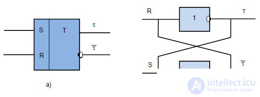
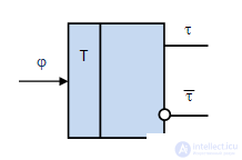
On charts, triggers are denoted as a rectangle divided into two fields. In the left field are the names of the inputs of the triggers (Fig. 6.2, a), in the right letter "T" there is a trigger with direct output  and inverse .
Fig. 6.2, b shows the implementation of the trigger using the NAND gate.
Work RS-trigger presented in Table 6.3.
| Inputs | States | ||
|---|---|---|---|
| RS | 0 | one | Operation |
| 0 0 | 0 | one | Storage |
| 0 1 | one | one | Set to 1 |
| ten | 0 | 0 | Set to 0 |
| eleven | Forbidden | ||
If the trigger is set to 1, then this value remains in it until a reset is effected (a signal is sent to the R -reset input) or the power is turned off. If the trigger is set to 0, then this value is stored in it until a signal is sent to the input S -set. Simultaneous sending of signals to both inputs of the trigger is prohibited, since in this case the situation is ambiguous. In more complex triggers, such as JK-triggers, this situation is excluded
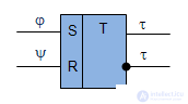
Denote the excitation function  and
and  which arrive respectively at the R and S inputs of the trigger (Figure 6.3) (Table 6.4). The work of the trigger will be represented by a transition table similarly to Table 6.2, i.e. We describe all transitions from the initial state of the trigger to possible transition states (Table 6.5).
 | ||
|---|---|---|
| RS | 0 | one |
| 0 0 | 0 | one |
| 0 1 | one | one |
| ten | 0 | 0 |
| eleven | - | - |
 | |  |
|---|---|---|
| 0 | 00v10 | 0 |
| 0 | 0 1 | one |
| one | 0 1 | 0 |
| one | 00v01 | one |
| | |
|---|---|---|
| 0 | - 0 | 0 |
| 0 | 0 1 | one |
| one | ten | 0 |
| one | 0 - | one |
Analyzing the table 6.5, we see that the trigger from the state "0" to the state "0" passes when both inputs are fed "0" or input S "0", and at the input R can be "1", that is, at the input S always with this transition must be "0", and at the input R any signal. Thus, the excitation functions at the transition of the trigger from "0" to "0" are:  ,
,  "-" (any signal). The trigger transition from the state "0" to the state "1" occurs if the input S is "1" and the input R must be "0", that is, the excitation function when the trigger transitions from "0" to "1":
  etc. All transitions and the corresponding excitation functions of the RS-trigger are shown in Table 6.6. This table is sometimes referred to as the RS Trigger excitation function table.
 | ||
|---|---|---|
| T | 0 | one |
| 0 | 0 | one |
| one | one | 0 |
 | |  |
|---|---|---|
| 0 | 0 | 0 |
| 0 | one | one |
| one | one | 0 |
| one | 0 | one |
 | ||
|---|---|---|
| D | 0 | one |
| 0 | 0 | 0 |
| one | one | one |
| | |
|---|---|---|
| 0 | 0 | 0 |
| 0 | one | one |
| one | 0 | 0 |
| one | one | one |
Clocked trigger, the output of which "switches", that is, changes the current state to the opposite with each receipt of the active signal "1". The operation of the T-trigger is described in Table 6.7, the representation of which for the explicit mapping of the excitation function of the T Trigger is given in Table 6.8.  , only when the state of the automaton goes from 0 to 1 or from 1 to 0.
D-trigger (Fig.6.5) has the installation modes "1" and "0" and implements the function of the time delay (Table 6.8). As you can see from the tab.6.9 function of Fig.6.5 excitation of D - trigger  coincides with the state in which the trigger switches.

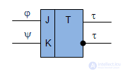
The most widely used is the universal JK-trigger (Fig.6.6). Work JK-trigger presented in Table 6.11. Simultaneous signaling at both inputs of the trigger causes it to work as a T-trigger, that is, if the trigger has been set to "0", then it switches to "1" and vice versa.
| Inputs | States | ||
|---|---|---|---|
| Jk | 0 | one | Operation |
| 0 0 | 0 | one | Storage |
| 0 1 | 0 | 0 | Set to "0" |
| ten | one | one | Set to "1" |
| eleven | one | 0 | Switching |
Denote the excitation function and  which arrive respectively at the J and K inputs of the trigger (Fig.6.6) and (Table 6.11). The work of the trigger will be represented by a table (Table 6.12) and tables of excitation functions (Table 6.13) and (Table 6.14).
| ||
|---|---|---|
| Jk | 0 | one |
| 0 0 | 0 | one |
| ten | one | one |
| eleven | one | 0 |
| 0 1 | 0 | 0 |
| | |
|---|---|---|
| 0 | 00v01 | 0 |
| 0 | 10v11 | one |
| one | 01v11 | 0 |
| one | 00v10 | one |
| | |
|---|---|---|
| 0 | 0 - | 0 |
| 0 | one - | one |
| one | - one | 0 |
| one | - 0 | one |
Analyzing the table 6.11, we see that the trigger from the state "0" to the state "1" passes when the input "K" is "1", and any signal can be input J. The transition of the trigger from the state "1" to the state "0" occurs if the input J is "1" and the input K is any signal. Thus, the excitation functions are as follows:  , at transition of the trigger from "1" to "0" and
  at transition of the trigger from "0" in "1".

Comments
To leave a comment
Theory of Automata
Terms: Theory of Automata