Lecture
We briefly note the main stages of the synthesis of the automaton:
 (M is the number of states of the abstract automaton) and we encode the states of the abstract automaton.
 Let us consider the synthesis of the structural automaton Moore given by Table 7.1.1 on D-triggers in the elemental basis {AND, OR, NOT}.
| u | u1 | u2 | u3 | u1 |
|---|---|---|---|---|
| z \ a | a1 | a2 | a3 | a4 |
| z1 | a1 | a3 | a1 | - |
| z2 | - | a1 | a4 | a2 |
| z3 | a4 | a2 | a3 | a3 |
 and encode the state of the abstract automaton, for example, as shown in Table 7.2.
  |  | |
|---|---|---|
| a 1 | 0 | 0 |
| a 2 | 0 | one |
| a 3 | one | 0 |
| a 4 | one | one |
| X 1 | X 2 | |
|---|---|---|
| z 1 | 0 | one |
| z 2 | one | 0 |
| z 3 | one | one |
| r 1 | r 2 | |
|---|---|---|
| u 1 | 0 | 0 |
| u 2 | 0 | one |
| u 3 | one | 0 |
| r 1 r 2 | 00 | 01 | ten | 00 |
|---|---|---|---|---|
x 1 x 2 \  | 00 | 01 | ten | eleven |
| 01 | 00 | ten | 00 | - |
| ten | - | 00 | eleven | 01 |
| eleven | eleven | 01 | ten | ten |
The output function r 1 , which depends on Moore’s automaton only on the state, takes a single value on a single set of 10, i.e.  . The output function r 2 takes a single value also on a single set of 01, i.e.
  .
.
Thus, the equations of outputs:
 ,
,
 .
.
 .
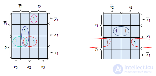
. The first unit value of the excitation function takes upon transition from the state a 0 , encoded as 00, i.e.  , at receipt of single input signals
  . Similarly, we find the remaining terms and write the excitation function of the first trigger:

For the second trigger of transition states in which it takes single values, four. They are highlighted in dark red. According to them recorded the excitation function of the second trigger:


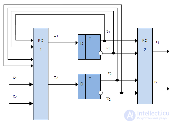
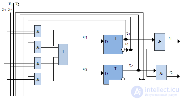
Using the obtained equations for the excitation functions and outputs, we construct a functional-logic circuit (Fig. 7.3).
The stages of coding, the construction of a generalized scheme, the construction of equations of outputs coincide with the stages of synthesis on D-triggers. Consider the construction of the equations of excitation functions, that is, starting from the fifth stage.
 |  |  |
|---|---|---|
| 0 | 0 | 0 |
| 0 | one | one |
| one | one | 0 |
| one | 0 | one |
| r 1 r 2 | 00 | 01 | ten | 00 |
|---|---|---|---|---|
 | 00 | 01 | ten | eleven |
| 01 | 00 | ten | 00 | - |
| ten | - | 00 | eleven | 01 |
| eleven | eleven | 01 | ten | ten |
 | 00 | 01 | ten | eleven |
|---|---|---|---|---|
| 01 | 00 | eleven | ten | - |
| ten | - | 01 | 01 | ten |
| eleven | eleven | 00 | 00 | 01 |
Since the excitation function of the T-trigger (Table 7.6)  , only when the state of the automaton goes from 0 to 1 or from 1 to 0, then using the encoded Fig.7.7 transitions of the original Moore's automaton, we find such trigger switches for which they change their states. We compile a table of excitation functions, which has state codes as column headings, and rows are labeled with input signal codes (Table 7.8). In each cell of the table recorded excitation function
  We make the equations for them:

Further, the equations are minimized and a scheme is constructed using them in a given basis.
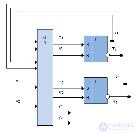
Consider the synthesis of the structural Mile automaton given by Table 7.9 and Table 7.10 on RS triggers in the elemental basis {AND, OR, NOT}.
| z \ a | a1 | a2 | a3 | a4 |
|---|---|---|---|---|
| z1 | a1 | a3 | a1 | - |
| z2 | - | a1 | a4 | a2 |
| z3 | a4 | a2 | a3 | a3 |
| z \ a | a1 | a2 | a3 | a4 |
|---|---|---|---|---|
| z1 | w1 | w3 | w1 | - |
| z2 | - | w1 | w2 | w2 |
| z3 | w2 | w2 | w3 | w3 |
| t 1 | t 2 | |
|---|---|---|
| a 1 | 0 | 0 |
| a 2 | 0 | one |
| a 3 | one | 0 |
| a 4 | one | one |
| x 1 | x 2 | |
|---|---|---|
| z 1 | 0 | one |
| z 2 | one | 0 |
| z 3 | one | one |
| y 1 | y 2 | |
|---|---|---|
| w 1 | 0 | 0 |
| w 2 | 0 | one |
| w 3 | one | 0 |

| x 1 x 2 \ t 1 t 2 | 00 | 01 | ten | eleven |
|---|---|---|---|---|
| 01 | 00 | ten | 00 | - |
| ten | - | 00 | 01 | 01 |
| eleven | 01 | 01 | ten | ten |
| r 1 r 2 | 00 | 01 | ten | 00 |
|---|---|---|---|---|
| x 1 x 2 \ t 1 t 2 | 00 | 01 | ten | eleven |
| 01 | 00 | ten | 00 | - |
| ten | - | 00 | eleven | 01 |
| eleven | eleven | 01 | ten | ten |
The excitation function of the RS-trigger is presented in table 7.16. Looking through each transition of triggers on the transition table of the machine (Table 7.15), we compose a table of excitation functions (Table 7.17), which has state codes as column headings, and rows are labeled with input signal codes. In each cell of the table, the excitation functions are written for the first trigger  and for the second trigger
  . We make the equations for them:
|  | |
|---|---|---|
| 0 | 0 - | 0 |
| 0 | ten | one |
| one | 0 1 | 0 |
| one | - 0 | one |
 | 0 0 | 0 1 | ten | eleven |
|---|---|---|---|---|
| 01 | 0- 0- | 10 01 | 01 0- | - |
| ten | - | 0- 01 | -0 10 | 01 -0 |
| eleven | 10 10 | 0- -0 | -0 0- | -0 01 |

Further, the equations are minimized and a scheme is constructed using them in a given basis.
Similarly, the synthesis is carried out on JK triggers.

Comments
To leave a comment
Theory of Automata
Terms: Theory of Automata