Abstract: The synthesis of a structural automaton is considered graphically. Concrete examples of synthesis are given. As memory elements are used RS-triggers JK - triggers, T-triggers, D - triggers.
Keywords: automaton, graph, abstract automaton, graph vertices, function value, true, arc, D-flip-flop, basis, Mili automaton, RS, minimization, Moore automaton, JK
8.1 Stages of the graphical method for the synthesis of a structural automaton
The first three stages of the graphical method of synthesis coincide with the tabular method. The abstract automaton is represented as a graph.
- Find the number of memory elements
 , (
, (  - the number of states of the abstract automaton) and we encode the states of the abstract automaton.
 - Encode input and output signals.
- The structural automaton is represented by a generalized scheme.
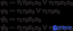
- Making equations of output functions.
We represent the coded graph of the abstract automaton, that is, instead of the states of the automaton, the corresponding code combinations are indicated, and the input signals are indicated on the transitions by their own logical code combinations. Logical code combinations of the output signals of the first kind are recorded on the transitions, and the signals of the second kind are recorded as state labels (or inside the top of the graph). Moreover, for output functions, only those values of functions should be specified, which take the true values by which the equations of the outputs are compiled.
- Making equations of excitation functions.
On the coded graph on the arcs of the transition, we indicate the excitation functions that correspond to the trigger switching, and only those values of the functions that take true values should be indicated, from which the equations of the excitation functions are compiled.
- The equations of excitation functions and outputs are minimized (using Carnot cards, for example) and a circuit is constructed from them in a given functional-logical basis ({AND, OR, NOT}, {AND-NO}, {OR-NOT}).
8.2 Example of a graphical method for the synthesis of a structural automaton
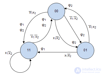
Let Miles machine gun be given (Fig. 8.1). Perform the synthesis of a structural automaton on RS - triggers.
- the number of triggers is equal to
 ). The states of the abstract automaton are encoded as shown in tab. 8.1.
 Table 8.1.  |  |
|---|
| a 1 | 00 |
|---|
| a 2 | 01 |
|---|
| a 3 | eleven |
|---|
- We encode the input and output signals, for example, as shown in Table 8.2 and Table 8.3.
Table 8.2. | z i \ x 1 x 2 | x 1 \ x 2 |
|---|
| z 1 | 00 |
|---|
| z 2 | 01 |
|---|
| z 3 | ten |
|---|
Table 8.3. | w i \ y 1 y 2 | y 1 \ y 2 |
|---|
| w 1 | ten |
|---|
| w 2 | 00 |
|---|
| w 3 | eleven |
|---|
| w 4 | 01 |
|---|
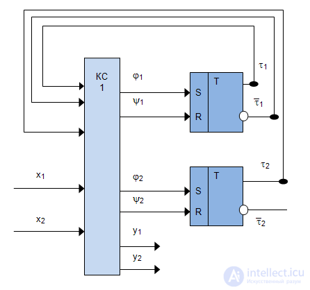
- The structural automaton is represented by a generalized scheme (Fig. 8.2).
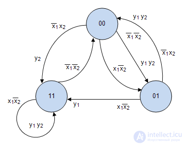
- We represent the coded graph of the abstract automaton (Fig. 8.3), that is, instead of the states of the automaton, the corresponding code combinations are indicated, and the input signals are indicated on the transitions by their logical code combinations. Logical code combinations of the output signals of the first kind are recorded on the transitions, and the signals of the second kind are recorded as state labels (or inside the top of the graph). Moreover, for output functions, only the key values of the functions should be specified, which take the true values by which the equations of the outputs are compiled.

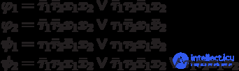
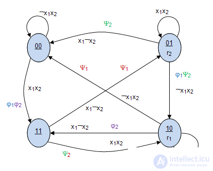
- Making equations of excitation functions for RS - trigger. On the coded graph on the arcs of the transition indicate the excitation function:
 if the 1st trigger has switched from 0 to 1;
  if the 2nd trigger has switched from 0 to 1;
  if the 1st trigger has switched from 1 to 0;
  if the 2nd trigger has switched from 1 to 0; (Fig.8.4).
 The equations of the excitation functions will be:
- The last stage of minimization of equations, the construction of the scheme is performed as in previous cases of synthesis.
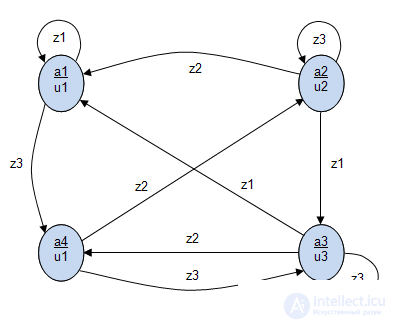
8.3 Example of a graphical method for the synthesis of Moore's structural automaton
Let Moore's automaton be given (Fig. 8.5). Perform the synthesis of a structural automaton on JK triggers.
- the number of triggers is equal to
 . The states of the abstract automaton are encoded as shown in tab. 8.4.
 Table 8.4. |  |  |
|---|
| a 1 | 0 | 0 |
|---|
| a 2 | 0 | one |
|---|
| a 3 | one | 0 |
|---|
| a 4 | one | one |
|---|
- We encode the input and output signals, for example, as shown in Table 8.5 and Table 8.6.
Table 8.5. | x 1 | x 2 |
|---|
| z 1 | 0 | one |
|---|
| z 2 | one | 0 |
|---|
| z 3 | one | one |
|---|
Table 8.6. | r 1 | r 2 |
|---|
| u 1 | 0 | 0 |
|---|
| u 2 | 0 | one |
|---|
| u 3 | one | 0 |
|---|
- The structural automaton is represented by a generalized scheme (Fig. 8.6).
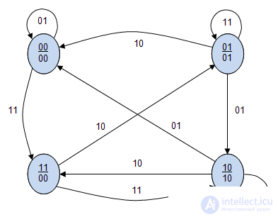
- We represent the coded graph of an abstract automaton (Fig. 8.7) and (Fig. 8.8). At the vertices we indicate only those values of the functions that take the true values, according to which the output equations are compiled
 .
. - Making equations of excitation functions for a JK trigger. On the coded graph on the arcs of the transition indicate the excitation function: if the 1st trigger has switched from 0 to 1; if the 2nd. trigger switched from 0 to 1; if the 1st trigger has switched from 1 to 0; if the 2nd trigger has switched from 1 to 0; (Fig.8.4).
The equations of the excitation functions will be:
- The last stage of minimization of equations, the construction of the scheme is performed as in previous cases of synthesis.


Comments
To leave a comment
Theory of Automata
Terms: Theory of Automata