Lecture
The execution of an educational assembly drawing of a product begins with clarifying the purpose of this product, its device and principle of operation, working position, ways of connecting the component parts, the sequence of assembly and disassembly.
For example, consider the valve gate assembly. Its purpose is to provide access to the working environment (for example, liquids) from one system to another. Opening and closing of the valve is provided by rotating the handwheel, respectively, counterclockwise and clockwise.
The valve must be disassembled into its component parts and allocate, if any, assembly units. Then you need to select the standard products directly in the product. It is necessary to establish the name of each part, its purpose in the assembly unit and the material from which the part is made.
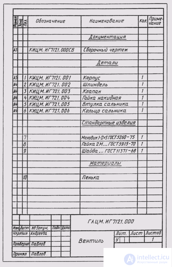
Fig. 319
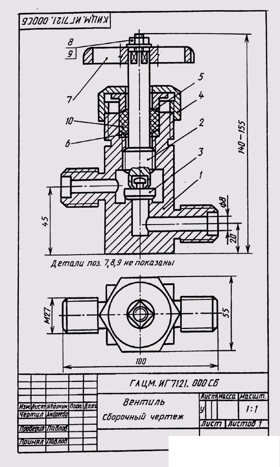
Fig. 320
It is recommended to make a diagram of the product with the allocation of the composition of the assembly units, the availability of parts of standard products, etc. In accordance with the scheme, make up the specification (Fig. 319). When designating the component parts of the product, it should be noted that the last three characters in the product designation or its document can be used as follows:
three zeros and the code number of the Security Council (000СБ) - for designation of the assembly drawing of the product;
the numbers 001,002,003, etc., to designate parts included in this product;
the numbers 100, 200, 300, etc., to designate the assembly units included in the item being specified;
numbers 101,102,103, etc. — to designate parts that are part of assembly unit 100, numbers 201, 202, 203, etc. — to identify parts that make up assembly unit 200, etc.
The drawing up of the assembly drawing is preceded by the work on drawing up sketches of all the parts included in the assembly unit (see §96).
Assembly drawing of the product is drawn from the sketches of parts. At a choice of scale of images the preference is given to the image of a product full-scale (M 1: 1). For small products (as in this example), you should apply the scale of increase, and for products of large sizes, the scale of reduction in accordance with GOST 2.302-68.
The number of images depends on the complexity of the product. For the subject in question, it is sufficient to perform a full longitudinal section in the place of the main view (Fig. 320) and a top view.
The construction should be carried out simultaneously on all the intended images, linking them with each other. The first one draws the main part (usually the case), and then the constructed images complement the details connected to the case.
On the sheet, all images must be placed freely in order to correctly dimension and number of positions. Position numbers are affixed in accordance with the completed specification.
In fig. 320 applied dimensions overall (140,100 and 55 mm), installation (20 and 40 mm) and mounting (M27).
At last, the main inscription is filled in and the necessary inscriptions are placed above the main inscription.

Comments
To leave a comment
16. Product Image
Terms: 16. Product Image