Lecture
Reading the assembly drawing is the process of determining the design, size and principle of operation of the product according to its drawing. We can recommend the following sequence of reading the assembly drawing of the product:
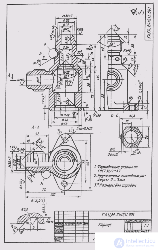
Fig. 321
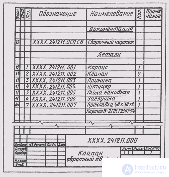
Fig. 322
determine the name of the product and scale of the image according to the main inscription
from the images to find out which types, sections, sections are made in the drawing and what is the purpose of each of them;
read the technical requirements of the drawing and dimensions;
according to the specification, determine the purpose of each part, its position in the drawing;
establish ways of connecting parts together and their interactions, determine the limits of movement of moving parts;
successively for each part included in the assembly unit, find out its geometric shapes and dimensions, i.e., determine the structure of the part;
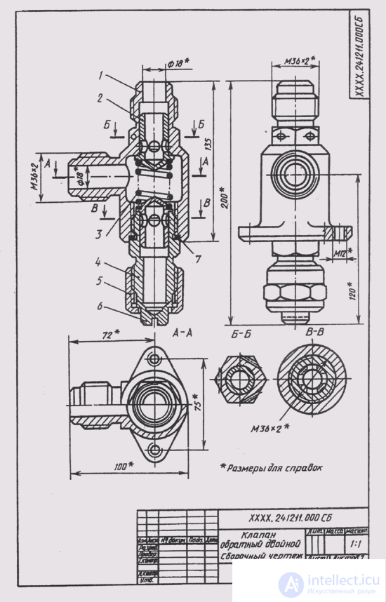
Fig. 323
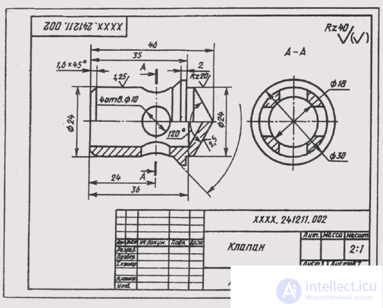
Fig. 324
mentally imagine the external, internal forms of the product as a whole and understand its work;
determine the order of assembly and disassembly of the product, i.e. the order of separation of one part from another, as it is done when dismantling the product.
Detailing is the process of making working drawings of the parts included in the product, according to the assembly drawing of the product. This is not a simple copy of part images from an assembly drawing, but a creative work.
The order of execution of the working drawing of the part according to the assembly drawing of the product is similar to the execution of the drawing of the part from nature. In this case, the shapes and dimensions of the part are determined when reading the assembly drawing.
The name of the part and its designation is determined by the specification of the assembly drawing, and the grade of the material - according to the description attached to the training assembly drawing.
The location of the part relative to the frontal plane of the projections, i.e. its main view, is selected on the basis of general requirements, and
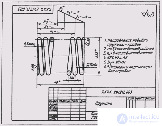
Fig. 325
not from its location on the assembly drawing. The number and content of the detail images may coincide with the assembly drawing.
The working drawing should show those elements of the part that are either not shown at all, or depicted in a simplified, conditional, schematic manner on the assembly drawing. These elements include:
foundry and stamping rounding, slope, taper;
grooves and grooves for the exit of the thread-cutting and grinding tools;
external, internal chamfers that facilitate the assembly of the product, etc.
Jacks for screws and studs on the assembly drawings are depicted in a simplified way, and on the working drawing the details of the socket must be drawn in accordance with GOST 10549-80.
The dimensions of the part are determined by measurements (if they are not marked on the drawing) according to the assembly drawing. At the same time it is necessary to ensure that the mating dimensions do not have discrepancies. Dimensions design

Fig. 326
Solid elements (chamfers, grooves, slopes, etc.) should be assigned according to the relevant standards, and not according to the assembly drawing.
The dimensions of the keyways, slots, studs and studs, screws, center holes and others should be taken from the relevant standards for these elements. The diameters of the holes for the passage of fasteners (screws, bolts, studs) should be affixed to the nature of the assembly.
The roughness of the surfaces of the parts is determined by the technical requirements, description, conditions of operation of the product and the part in the product.
To estimate and put down on the drawing the roughness of the surfaces of the part, it is necessary to determine whether this surface is conjugated or free, what is the nature of the operational requirements for it, etc. For typical parts, certain limits of roughness parameters are recommended.
In fig. 321 an assembly drawing of a double check valve is made; its specification is shown in fig. 322.
The principle of the valve is as follows. The liquid under pressure enters the hole diameter 18 of the upper tip of the housing 1, squeezing

Fig. 327
There is a spring 3, and into the gap between the valve 2 and the body enters through the diverting (to the left) tip of the body into the hydraulic system. If you remove the plug 7 from the lower tip of the housing, having screwed the cap nut 5, you can feed another liquid into the housing through the lower opening by connecting the valve to the second pipeline. In this case, a mixture of liquids will flow into the system.
Valve has no standard parts. Assembly drawing is made in 1: 1 scale.
In the place of the main view, a full longitudinal section of the valve is made with the frontal plane of symmetry of the product. This section allows you to identify the internal structure of all parts of the valve. In place of the top view, a combined image of a half of the view and a half of the horizontal sectioning - A by a plane passing through the axis of the body outlet tip. In the left view, a local cut is made along the threaded hole in the housing flange. In addition to these basic images, sections B - B and B - B are made . Section B - B shows the holes in the hexagonal part of the housing for sealing the valve after it is installed in the hydraulic system. Section B - B gives an idea of the mating parts 1, 2 and 4 and explains the location of the holes in the valve 2.
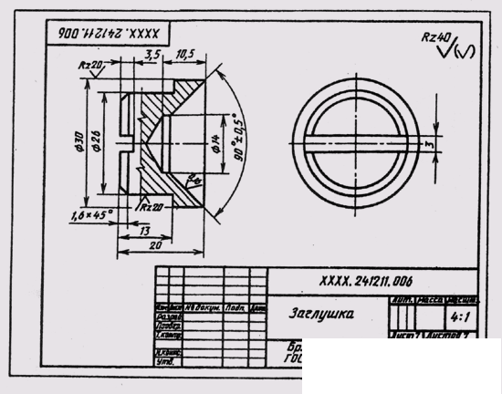
Fig. 328
The drawing shows overall dimensions (200 and 100 mm), installation (75 mm), mounting (M12 and M 36) and operational (diameter 18) dimensions.
Connections of parts in the valve are detachable, threaded. To ensure the density of the connection parts 2 and 4 in the groove parts 4 laid a strip of cardboard. The outer diameter of the gasket is 48 mm, the internal one is 38 mm, and the thickness is 3 mm (see pos. 7 of the specification in Fig. 322). Valves and plugs fit snugly to the surfaces of the body and fitting (they are ground). The connection of pipelines to the body is carried out using the thread M 36x2.
To disassemble the valve, it is necessary to unscrew the flare nut 5, and together with it remove the plug 6, unscrew the fitting 4 from the body , remove the gasket 7, remove both valves 2 and the spring 3 through the lower opening in the body. pursed and ground. Reassemble the valve in the reverse order.
In fig. 323–328, the working drawings of the parts included in the check valve are completed (Fig. 321).

Comments
To leave a comment
16. Product Image
Terms: 16. Product Image