Lecture
A graphic document defining the product design, the interaction of its main components and explaining the principle of the product, is called a general drawing. A general view drawing is developed in the first stages of design, that is, at the stage of technical proposal, draft and technical design.

Fig. 304
A general view drawing includes: an image, views, cuts, sections of the product, inscriptions and a text part necessary for understanding the constructive structure of the product, the interaction of its constituent parts and the principle of operation of the product; the name and designation of the component parts of the product, for which the principle of operation is explained, the technical characteristics, materials, quantity, and for those component parts of the product, with the help of which the principle of operation of the product is described, the images of the general appearance and the composition of the product are explained; required dimensions; product schema and specifications.
The drawing of the general form is carried out in compliance with the requirements of GOST 2.109-73. Components are depicted in a simplified way. They can be depicted on a single sheet with a general view or on separate subsequent sheets.
The name and designation of the component parts of the product can be indicated in one of the following ways:
on the shelves of the callout lines drawn from the parts in the general view drawing;
in the table placed on the general view drawing (Fig. 304);
in the table, made on separate sheets of A4 format, as the following sheets of the general view drawing.
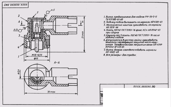
Fig. 305
If there is a table, the sequence number of the component parts of the product is indicated on the shelves of the callout lines in accordance with this table.
The table is placed above the main inscription of the drawing.
The text part in the form of technical requirements and technical specifications must necessarily be placed on the first sheet in the form of a column not exceeding 185 mm wide. If necessary, the text is placed in one, two or more columns. In this case, the second and last columns are located to the left of the main label. You cannot place images or other tables between the text part and the component parts table (or the title block).
On the drawing of a general view, they affix the overall, connecting, installation and necessary structural dimensions (Fig. 305).
The necessary tables, including technical specifications, arranged in the form of a table, are placed on the free field of the general view drawing to the right of or below the images. If there are several tables and they are referenced in the technical requirements, the tables are labeled as: “Table 1” (without the number sign).
All tables are filled from top to bottom.

Comments
To leave a comment
16. Product Image
Terms: 16. Product Image