Lecture
Graphic document, which shows in the form of conventional images and symbols of the component parts of the product and the relationship between them in accordance with GOST 2.102-68, called the scheme.
Types and types of schemes, general requirements for their implementation are regulated by GOST 2.701—84.
Schemes facilitate the study of the device products. Depending on the types of elements that make up the product, and the connections between them, the schemes are divided into electric (E), hydraulic (G), pneumatic (FT), kinematic (K), optical (L), etc.
Depending on the main purpose, the schemes are divided into the following types: structural (7), functional (2), basic (3), connections (4), connections (5), etc.
The structural diagram defines the main functional parts of the product, their purpose and relationship.
The functional diagram explains the processes occurring in individual functional circuits of the product or in the product as a whole.
The principal (complete) scheme determines the complete composition of the elements and the connections between them in the product, gives a detailed idea of the principles of operation of the product.
The connection diagram (assembly) shows the connections of the component parts of the product and identifies the wires, cables, pipelines that make these connections, as well as the points of their connection.
The name of the scheme is determined by its type and type, and the code of the scheme consists of a letter identifying the type of scheme and a number designating its type. For example, the electric circuit has the cipher EZ. If there is a scheme for which the code K1 is written in the designation, this means that the kinematic structural scheme is executed.
Schemes are executed out of scale. Communication lines are 0.2 ... 0.4 mm thick, trying to avoid a large number of their intersections and kinks. The distance between adjacent parallel lines of communication must be at least 3 mm.
If there are thickened lines in the conventional graphic symbols, they are drawn twice as thick as the communication lines.
The circuit elements constituting a functional group or device that do not have an independent concept can be distinguished by dash-dotted lines, the thickness of which is equal to the thickness of the received communication lines. The diagram indicates the name of these groups, for example, the gearbox, caliper, etc.
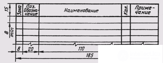
Fig. 329
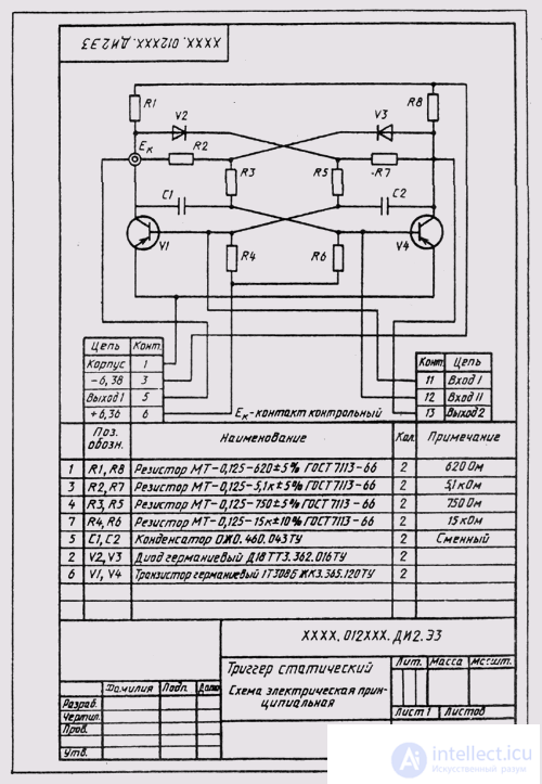
Fig. 330
The circuit elements that make up the device, having an independent schematic diagram, are distinguished on the general schematic diagram by a solid thin line equal in thickness to the communication lines.
It is allowed to place on the scheme various technical data characterizing the scheme as a whole and its individual elements. This information is placed either near the graphic symbols, or above the main title.
Electrical concepts (EZ) are performed in accordance with GOST 2.702-75. The designations in the electrical circuits are set GOST 2.721-74 - GOST 2.791-74.
Schemes drawn in the off state. Symbols in the diagram are drawn in the position in which they are depicted in the relevant standard, or rotated by an angle of 90 times with respect to this position.
All elements on the scheme must be uniquely determined. To do this, the data on the elements are recorded in a table (Fig. 329), which is filled from top to bottom and placed on the first sheet or executed as an independent document on A4 format.
Each element of the scheme should have a reference designation, which includes a letter designation and a sequence number (Fig. 330). The letter designation: resistor - R, capacitor - C, inductance coil - L, ammeter - A, voltmeter — V, generator — G, semiconductor diode— D, choke— Other, button - Kn, electronic device — D motor (motor) - M, fuse— Pr, relay - P, semiconductor triode - T, transformer - Tr , etc.
Positional symbols are applied next to the conventional symbol to the right of it or above it. The sequence number is assigned in accordance with the sequence of elements from top to bottom and from right to left.
The elements are written into the table in groups in order of their location in the annex to GOST 2.702-75, i.e., resistors are first recorded, then capacitors, inductors, ammeters, etc., are recorded. Within each group, the elements are arranged in ascending order numbers. Elements of the same type with the same electrical parameters, having consecutive sequence numbers on the diagram, may be written in the “Pos.” Column in one line, by type: C 1 ... C 4 , and in the “Kol.” Column the total number of such elements .
It is recommended to indicate on the scheme the characteristics of the input and output circuits of the product: frequency, voltage, amperage, etc., as well as the parameters to be measured at control contacts, sockets, etc. The characteristics of the input and output circuits of the product are recorded in a table.
On the field of the electrical concept it is allowed to place instructions on the marks, sections and colors of wires and cables, as well as instructions on the specific requirements for electrical installation of the product.
Kinematic concepts (CG) show the sequence of motion transmission from the engine through the transmission mechanism to the working bodies or instruments, and also make it possible to judge the ways of their regulation, control, and control.
Kinematic schemes are performed in accordance with GOST 2.703-68. The kinematic scheme shows all the kinematic elements of the product, reflects the kinematic relations of the mechanical and non-mechanical type between the various elements and groups of elements of the product, shows the connection of the mechanism with the engine.
Elements of kinematic schemes are denoted conditionally according to GOST 2.770-68. Kinematic elements include shafts, axles, bearings, couplings, brakes, pulleys, gears, worm gears, etc.
The kinematic scheme is drawn in the form of a sweep and does not give the spatial (three-dimensional) arrangement of the component parts of the product. With complex spatial kinematics, it is recommended to depict the scheme in axonometric projections.
On the kinematic scheme, you can arrange a scheme of another type, directly affecting the operation of the product.
Each kinematic element is assigned a sequence number, starting from the engine. The sequence number is placed on the shelf of the callout line, and under the shelf indicate the main characteristics and parameters of the kinematic element. The shafts are numbered in Roman numerals, the remaining elements are Arabic.
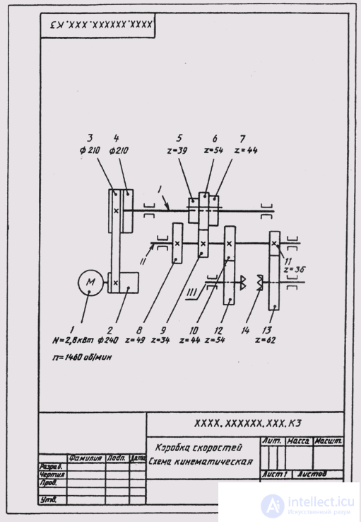
Fig. 331
The symbols on the diagram are drawn without adhering to the scale of the image. However, if you repeat the same characters, you need to do them the same way. The ratio of the sizes of conventional symbols should approximately correspond to the actual ratio of their sizes.
The mutual arrangement of elements on the kinematic scheme should correspond to the initial, average or operating position of the executive bodies. The extreme positions of the moving elements are indicated by thin dash-dotted lines.
The shafts, axes, rods on the kinematic diagrams are depicted as solid main lines with the thickness S; elements depicted by external contours, gears, worms, sprockets, pulleys, cams - solid lines 5/2 thick; the contour of the product in which the scheme is inscribed is in continuous thin lines with a thickness from 5/3 to 5/2.
On the kinematic schemes it is allowed to indicate: the names of each group of elements having a certain functional value; the main characteristics and parameters of kinematic elements (for the engine - type, power, rotational speed, for gears - the number of teeth and module, etc.); reference and calculated data in the form of graphs, charts, tables.
If the scheme has gears, then the wheels are considered to be transparent, as it were, and it is conditionally assumed that they do not close each other.
Reading the kinematic scheme starts from the engine, identifying each element of the kinematic chain sequentially by the symbols, establishing its value and the nature of motion transmission. Reading the scheme is recommended to begin with the study of the passport of this mechanism. In fig. 331 shows the kinematic diagram of the speed box of the lathe.

Comments
To leave a comment
16. Product Image
Terms: 16. Product Image