Lecture
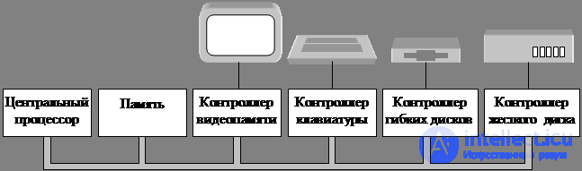
Fig. 2.1. Some components of a personal computer
The processor . Processor: own command set + own registers + RON.
One of RON is PSW (Processor Status Word). Contains service information.
User programs can read the entire PSW register, but they can only write to some of its fields. Important for system calls and I / O operations. Most CPUs, in addition to very simple (in embedded systems), have two (four Intel) operating modes: kernel mode and user mode. The mode is set by the processor state word (PSW) bit. A processor running in kernel mode can execute all commands and use all the capabilities of the hardware. In user mode: a subset of commands, a piece of hardware. Setting the mode bit manually is not available.
To communicate with the operating system, the user program must form a system call that provides a transition to the kernel mode and activates the OS functions. After the completion of the operation, control returns to the user program, to the command following the system call.
In addition to system calls, there are other interrupts: division by zero, overflow, and floating point operations. All these cases are resolved by the OS.
Processors: sampling (n + 2 command), decoding (n + 1 command) and execution (n - command) at the same time - pipeline .
Super-scalar architecture - in one clock cycle, two or more commands are read, and they are dropped into the storage buffer. They are not chosen in the order of succession, but the equipment must guarantee the result identical with the sequential scheme. These complications relate to the operating system.
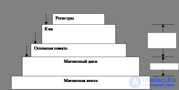
Memory. The ideal of memory: fast, big enough and cheap. Memory is a hierarchy of layers.
The upper layer is the internal registers of the central processor. The programs themselves can manage the registers without hardware intervention. The size is 32 * 32 bits (32-bit processor), 64 * 64 bits (64-bit).
The next layer is the cache. It is divided into cache lines, 64 bytes each. The high-speed cache is located inside the CPU or very close to it. When reading a word, the microcircuit checks for the presence of the required line, if there is, then the call takes two clocks, if not, there is a significant loss of time (depending on the processor speed). There are two cache levels, with each subsequent slower and more than the previous one. The first cache is for selecting processor commands, the second for user programs.
The last layer in the pyramid is the magnetic tape — the storage of backup copies of the hard disk. The process of rewinding (access) minutes. Cheap.
RAM . Ram . The main working area of the storage device of the machine.
Disk memory is two orders of magnitude cheaper than RAM in terms of bits and often two orders of magnitude more.
ROM is programmed during production. Fast and cheap memory.
Electrically erasable ROM and Flash RAM are non - volatile, they can be used to correct errors contained in programs. Writing slower than RAM
CMOS memory is non-volatile, used to store the current date and time. CMOS- memory + clock chip, responsible for counting time, receive power from a small battery. CMOS memory can also contain configuration parameters indicating which disk to boot from.
Main programs are more convenient to keep in memory. With regard to the management of RAM, while finding several programs at the same time, it becomes necessary to solve two problems:
1) Protection of programs from each other, and the kernel from them;
2) Manage the movement of programs in memory.
In the process of compiling and linking, the compiler and linker do not know in which area of physical memory the program will be loaded after the completion of the compilation process. It is assumed that from the 0th adlres will begin and place the first instruction there. The solution to the problem: supplying the processor with special equipment. The simplest solution: base and limit registers. The base register loads the beginning of the executable module of the program, and the limit register loads the program module along with the data it occupies; it prohibits referring to any area after the program. As a result of verification and conversion, this address formed by the program is called virtual , is translated to the address used by the memory and called physical . MMU checks and translates addresses.
There may be a more complex dispatcher, which consists of two pairs of base and limit registers: one for text and the other for data. The command register and all other references to the text of the program work with pair 1, and the links to the data use pair 2. It becomes possible to divide this program between different users and to keep in memory only one copy of the program, which was impossible in the first diagram.
So, managing the memory manager should be a function of the operating system.
There are two aspects that affect memory performance. First, the cache hides the relatively low memory speed. Worked for some time the program fills the cache. However, when switching from one program to another, the cache is filled with the data of the first program. If such an operation occurs frequently, it is the cause of poor performance.
Secondly, when switching from one program to another, the memory management registers should change. In the second case, only four registers need to be reset, but in real dispatchers, they are usually much more. Switching takes time, is called context switching .
I / O device. I / O devices typically consist of a controller and the device itself. A controller is a microcircuit or a chipset on a board inserted into a connector that physically controls the device.
The controller includes a simple interface for the operating system. The disk controller accepts the command to read sector 11206 from disk 2. In this case, the controller must convert the linear sector number into the cylinder, sector and head number, etc. To accomplish this, controllers contain small built-in pre-programmed computers.
The next part is the device itself. Devices have interfaces, for example, the IDE standard (E IDE) - built-in storage interface for computers with a Pentium processor. This device interface is hidden by the controller, the OS only sees the controller interface.
A program that communicates with a controller is called a device driver . Each controller manufacturer must supply drivers, the structure of the driver depends on the structure of the operating system it supports. Therefore, for the scanner there may be drivers for Windows 98, 2000 UNIX. The driver is installed in the OS so that it can work in kernel mode. There are three ways to install the driver in the kernel. First : rebuild the kernel and then reboot the UNIX system. Second , make a record in the OS file that the driver is required and then reboot the system. During the initial boot, the OS itself finds the necessary drivers and loads them. This is the work of Windows. The third way: the operating system itself accepts the necessary drivers without interrupting work, quickly installs them, without needing to reboot. The method is becoming more and more common. Such devices as USBIEEE 1394 buses need only dynamically loaded drivers.
For communication with each controller there is a small number of registers. For example, the minimum disk controller can have registers for determining the disk address, memory address, sector number, and the direction of the operation: read or write.
Data input and output can be done in three different ways. The simplest method is that the user program issues a system request that the operating system translates to the procedure call of the corresponding driver. The driver then begins the I / O process. At this time, the driver starts a short software cycle, constantly polling the readiness of the device with which it works (usually there is some bit that indicates that the device is still busy). Upon completion of the input – output operation, the driver places the data where it is needed and returns to its original state. The operating system then returns control to the program making the call. The method is called waiting for readiness or active waiting and has one drawback: the processor must interrogate the device until it completes its work.
In the second method, the driver starts the device and asks him to issue an interrupt after the I / O ends. After that, the driver transmits the data, the operating system blocks the calling program, if necessary, and begins to perform other tasks. When the controller detects the end of the data transfer, it generates an interrupt to signal the completion of the operation.
Three-step input / output process. In the first step, the driver sends a command to the controller, writing information to the device registers. Then the controller starts the device. When the controller finishes reading or writing the number of bytes that it was instructed to transmit, it sends a signal to the interrupt controller chip using certain bus wires, this is step 2. In step 3, if the interrupt controller is ready to receive the interrupt ( and this may not be the case if it is busy interrupting a higher priority, it sends a signal to a certain processor contact, thus informing the central processor. In step 4, the interrupt controller sets the number Bus devices so that the CPU can read and find out which device has just completed its work (several devices can work at the same time.) The device number can be used as an index of a part of memory used to find the interrupt handler address of this device. This part of the memory is called the interrupt vector .
The third I / O method is to use a dedicated direct memory access (DMA) controller, which controls the flow of bits between the RAM and some controllers without the constant intervention of the central processor. The processor calls a microchip (DMA), tells it how many bytes to transmit, reports the device and memory addresses, as well as the direction of transmission, and allows for further action itself. Upon completion, the DMA initiates an interrupt, which is processed in the same way as described above.
Interrupts often occur at very inappropriate moments, for example, while processing another interrupt. For this reason, the CPU has the ability to disable interrupts and allow them later. As long as interrupts are disabled, all devices that have completed work continue to send their signals, but the operation of the processor is not interrupted until all interruptions are resolved. If several devices finish their work at the same time, the interrupt controller decides which one should be processed first, usually based on the static priorities assigned to each device.
Tires. The structure shown in Figure 2.1 has been used for many years on minicomputers, as well as on the first models of the IBM PC. Machines have become faster to operate, one tire is clearly not enough. Additional tires to speed up communication with I / O devices, to transfer data between the processor and memory. Due to this evolution, the large Pentium system looks like this.
Eight buses (cache bus, local bus, memory bus, PCI, SCSI, USB, IDE, ISA), each with its own speed and its own functions. The OS for computer management and its configuration should collect information about all these tires. The two main ISA (Industry Standart Architecture - industrial standard architecture) –8.3 MHz –16.67 Mb / s, and PCI (Peripherial Component Interconnect –– peripheral interface) –– 66 MHz –528 MB / s - high-speed I / O devices .
With this configuration, the CPU transmits data on the local bus to the PCI bridge, which in turn refers to the dedicated memory bus — 100 MHz.
Pentium systems have a first-level cache embedded in the processor, and a much larger second-level cache connected to the processor by a separate cache bus.
Three specialized buses: IDE, USB and SCSI.
IDE - disks and CD-ROM.
USB - ( Universal Serial Bus - Universal Serial Bus) —slow I / O devices (keyboard, mouse) —load data at 1.5 MB / s. USB is a centralized bus where the host device polls the I / O devices every second to find out if they have data.
All USB devices use the same driver, so they can be connected to the system without rebooting.
SCSI (Small Computer System Interface - a system interface for small computers) is a high-performance bus used for fast disks, scanners, and others. 160 MB / s.
There is one more bus - IEEE 1394 Fire Wire 50 MB / s. Digital video cameras, multimedia devices, do not have a central controller.
Before the appearance of the “plag and play” standard, each board had fixed addresses of I / O registers and the interrupt request level. For example, the keyboard used interrupt 1 and addresses in the range 0x60..0x64, controller floppy disk interrupt 6 and addresses in the range 0x3F0 .. 0x3F7 and so on.
If a user accidentally bought a sound card and a modem, both devices accidentally used, for example, the 4th interrupt. They were in conflict. There was a need to build in DIP switches (jumpers) on each board and explain to the user the need to configure each board so that the addresses of the ports and the interrupt numbers of different devices do not conflict with each other.
Working in this environment Figure 2. The OS must recognize the hardware and be able to configure it. The plag and play standard allows the system to automatically collect information about I / O devices, centrally assign interrupt levels and I / O addresses, and then communicate this information to each board with this information to the board.
At boot time, the system BIOS starts. The BIOS is on the motherboard in flash RAM. First, it checks the size of the RAM, the presence of the main devices (keyboard, ...). BIOS starts checking with the ISA and PCI buses to determine all devices that are attached to them. Inherited devices are registered (fixed interrupt addresses and I / O port addresses), plag and play devices are registered.
The BIOS then determines the device from which the boot will occur, checking the list of CMOS memory in turn (floppy disk, CD, hard).
The OS then requests the BIOS, receiving configuration information. Check for drivers for each device. If all the drivers are in place, the OS loads them into the kernel, if not, it requests from a floppy disk or a compact disk. Then the driver tables are initialized, the necessary background processes are created, the program for entering a password or a graphical interface on each terminal is started.
3. System calls
System calls - the interface between the operating system and user programs. SV is the heart of the operating system, they talk about what the OS can really do. The system calls available in the interface vary from one operating system to another, although their concept is the same.
System calls are similar to the implementation of procedures, only the system call is executed in the address space of the kernel, and, therefore, in kernel mode.
Example: count = read (fd, buf, nbytes);
System calls are performed in a series of steps. First, when preparing to call the library procedure read, the caller pushes the parameters onto the stack (steps 1-3). Then: the actual library procedure call (step 4).
The library routine places the system call number in the register (where the operating system expects it) (step 5). Then switch to kernel mode (step 6). The kernel program being run uses a table of pointers to system call handlers, indexed by call numbers (step 7). Then the call handler begins to function (step 8). As soon as he completes his work, control returns to user space (step 9) to the command following the system call (step 10).
To complete the work, the user program must clear the stack, as is done after each procedure call (11). The stack grows down, it means that the stack pointer should be increased so that to remove the parameters placed on the stack under the read request.
Now the program can continue its work.
Programs access system calls by placing arguments in the CPU registers (or on the stack), executing an interrupt emulation command to transfer control of the OS and transition from user mode to kernel mode. It is impossible to write an emulated interrupt command in C, library functions do this, one per system call. Each such procedure puts the arguments in the right place and executes the command of the emulated TRAP interrupt. Thus, to access the read system call , a C program must call the read library function . The POSIX standard defines exactly the interface of library functions, and not the interface of system calls, they don’t even mention actual system calls.
Помимо ОС и библиотеки системных вызовов все версии содержат большое количество стандартных программ, некоторые описаны в стандарте POSIX 1003.2, многие могут различаться вразных версиях. К этим программам относится программный процессор (оболочка), компиляторы , редакторы, утилиты для работы с файлами.
Таким образом, три интерфейса в системе UNIX:
1) интерфейс системных вызовов;
2) интерфейс библиотечных функций;
3) интерфейс, образованный стандартным набором обслуживающих программ (который не имеет никакого отношения к системе и может быть легко заменен).
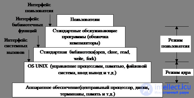
Fig. 1.2. Уровни операционной системы UNIX
Windows Win 32 API. Windows и UNIX - принципиально разные модели программирования. Программы UNIX выполняют те или иные действия, обращаясь к системе для предоставления тех или иных услуг. Программы в Windows приводятся в действие событиями. Основной модуль ждет, когда произойдет какое-либо событие, затем вызывает процедуру для его обработки, например, передвижение мыши, нажатие клавиатуры, появление гибкого диска в дисководе. Затем обработчики событий переписывают содержимое экрана и внутреннее состояние программы. Следствие – совершенно отличный от UNIX стиль программирования.
В Windows тоже есть системные вызовы. Однако, если в UNIX вызовы почти один к одному идентичны библиотечным процедурам, например, read. Кроме того, в стандарте POSIX около 100 процедурных вызовов. То в Windows, фактические системные вызовы и запускающиеся для их выполнения библиотечные вызовы полностью разделены. Для того, чтобы изменять системные вызовы от одной версии к другой, не делая недействительными существующие программы. Корпорация Microsoft определила набор процедур Win32 API, предполагается, что программисты должны использовать его для вызова служб операционной системы. Количество Win32 API – тысячи. Существенное число работает целиком в пространстве пользователя, какие – невозможно определить.
Если в UNIX графический интерфейс пользователя выполняется в пользовательском пространстве, то в Windows есть огромное количество вызовов для управления окнами, пунктами меню, другими элементами графики, и все это – системные вызовы, так как графическая подсистема запускается в режиме ядра. Однако, несмотря на то, что эти вызовы выполняются ядром, они не связаны с функциями операционной системы.
Примеры Win32 API : CreateProcess, CreateFile, ReadFile, CloseHandle.
Win32 API не является полностью единообразным и последовательным интерфейсом. Причина: необходимость совместимости c 16- разрядным интерфейсом Windows 3.х.
10. Purpose of the technology “plag and play” when connecting peripherals.

Comments
To leave a comment
Operating Systems and System Programming
Terms: Operating Systems and System Programming