Lecture
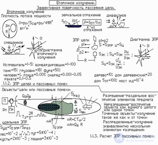
Fig. 2.1.1. Secondary radiation targets
Reaching the goal (object) of a microwave radio wave induces alternating currents of the same frequency in its construction elements. Moving through the elements of the object, the currents, in turn, begin to excite radio waves, which propagate from the target in different directions. In the centimeter wavelength range, the target may be tens of times greater than the radar wavelength. Therefore, the number of radiating elements can be large. Moreover, in a certain direction of space, the vector addition of voltages from each radiator will give different total levels.
If you “go around” the target around with the receiver, then you can register the secondary radiation and build a polar diagram of the secondary radiation.
“Going around” a goal can be done not only in one horizontal plane, but also in a vertical one. In general, a complex three-dimensional spatial picture of the secondary radiation diagram is formed around the target in the form of a so-called “spatial hedgehog”.
Part of the energy of the secondary radiation is directed towards the radar. It is believed that the larger the geometric dimensions of the target, the more it “intercepts” the microwave radiation of the radar, and the more it radiates into space. But not only the geometrical dimensions determine the radiation levels towards the station. Therefore adopted the term effective surface scattering (EPR) goal, which is often denoted by a small letter s .
S value can be compared with the amount of radiation, for example, some reference oriented square metal plate with an area of 1 m 2 . If the power of the received signal from the target is 10 times greater, then we can assume that the effective scattering surface of the target is s = 10 m 2 .
Cut a square out of metal, and then it is not always convenient to accurately align it with respect to the radar, so various geometric shapes are more often used as a reference. For example, the EPR of a triangular corner is easy to calculate on the known side of the corner. Often used ball with a known radius. It does not need to be oriented at all.
The table below shows examples of EPR of various objects.
Now we will understand how to emit targets depending on their position relative to the radar. Connect the line and the station. Set the target on the line in the direction of the radar by any side, for example, the hood (for auto technology). By consistently turning the target relative to the radar by an angle, for example, 1 degree, it is possible to register the reflected signal levels in the direction of the radar. The power of the reflected signal can be represented in the form of a polar diagram. After normalization with a reference signal, you can get a figure that is called a secondary diagram radiation target, or an EPR diagram.

Comments
To leave a comment
Radio Engineering Systems
Terms: Radio Engineering Systems