What is the radio range and what does it depend on? To answer this question, it is necessary to recall the role of the antenna of the transmitter and the receiver. The transmitter antenna not only radiates radio waves, but also concentrates the power of the stream in the right direction. This feature is characterized by antenna gain G a . Indirectly, this value is related to the width of the antenna diagram Q a , or its directivity factor KND, as well as the efficiency η (efficiency), which reflects the magnitude of the losses in the transmission line and the utilization of the surface of the antenna design.
The amount of energy intercepted by the antenna of the radio receiver depends on the area of the receiving antenna S a . The same, in turn, is also associated with the gain and wavelength λ. The wavelength has to be taken into account, since at a shorter length a greater gain can be obtained with the same area, although the ability to intercept the radio wave will remain the same. We present relations known from the theory of antenna systems, and we will use, in justified cases, also empirical relations for engineering calculations.
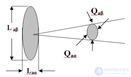
Fig.1. Parameters of the mirror antenna
CPD = 360 o 360 o / [ Q aα o Q aβ o ] ; G a = KND * η; S a = G a λ 2 / (4π) (one)
G a ≈ (10-25) 10 3 / ( Q aα o Q aβ o ) ; L aβ ≈ (60-80) λ / Q aβ o ; L aα ≈ (60-80) λ / Q aα o
Examples:
Antenna type gain
Mirror 1,5h3,5 grad 2cm 3500
Half Wave Vibrator 1.5
Quarter wave vibrator one
An important indicator of radio range is the power flux density γ. It shows how much radio wave power in watts accounts for one square meter of the surface of the sphere of radiation.
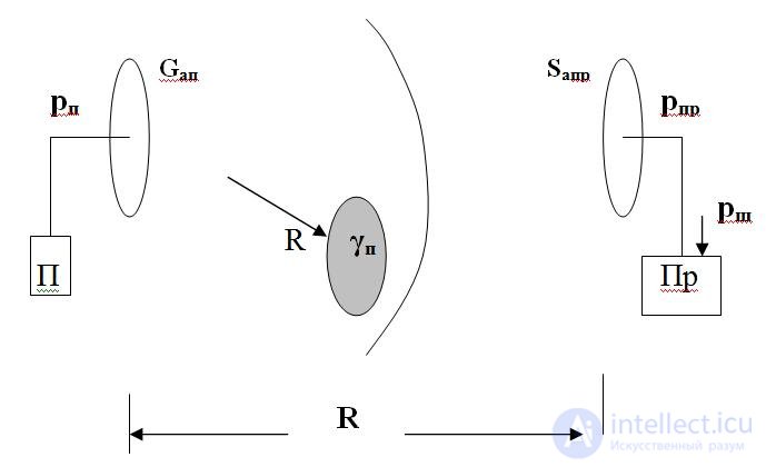
Fig. 2. To derive a radio equation
A point emitter radiates spherical radio waves. At a distance R from it, the signal power of the transmitter in the antenna p p is divided by the entire area of the sphere 4π R 2 . Therefore, one square meter of the sphere will have the power flux density γ p = p p / ( 4π R 2 ). If the antenna has a known gain factor G a p , the flux density will increase by the same amount γ p = p p G a p / ( 4π R 2 ) .
The antenna of the receiver intercepts part of the stream and the received signal power is generated in it S a From here it is possible to calculate the power of the received signal taking into account the dependence of the area of the antenna on the gain factor from equalities (1):
p pr = S a pr p p G a p / (4π R 2 ) = p p G a p G a pr λ 2 / (4π) 2 R 2 (2)
Relationship (2) is the first form of a radio equation. It is possible to calculate the signal power at the input of the receiver of the receiving station. But we must not forget that electrical noise is generated in the receiver. Their power can be brought to the input, as was previously shown in the lecture LekzRT 1.3. The power of the reduced noise in watts
calculated taking into account the frequency bandwidth of the receiver ∆ F pr and its noise properties.
p w = n sh 2 ∆ F pr ; p w = NkT ∆ F pr (3)
In equations (3) n w The spectral density of the noise voltage at the input to V / Hz, n W 2 is the same on the W / Hz scale. N - receiver noise figure, kT - Boltzmann constant and conditional receiver noise temperature in degrees. Kelvin
The spectral power density n W 2 can be found in the references for receiving devices, as well as the noise temperature. The noise factors of the receiving devices are also one of the important characteristics and are indicated in the passports for the products.
Return to the probabilities of detection and false P about alarms r lt . Neither depends on the signal-to-noise ratio and the threshold level Un of the automatic detector. Engineers have optimized the threshold level for various requirements for P about and Рлт and received the so-called receiver performance. Their appearance is given in fig. 3
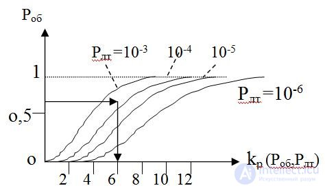
rice 3. Receiver performance
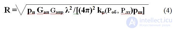
The potential for qualitative reception of information depends on the distinctiveness k p (P on , P lt ) of the signal against the background noise, that is, on the signal-to-noise ratio that is provided by the radio transmission channel. In fig. 3 an example is given of how the required signal-to-noise ratio is estimated as a function of the given values of Р об , Р лт. Thus, the transmitter power P p with the known characteristics of the antennas and the wavelength must be such that the one found from the curves in Fig. 2 is provided. 3 k p . That is, the condition p pr > = k p p w. Taking into account the latter, it is possible to obtain the second form of the radio communication equation, according to which the range of the radio communication can be calculated.

Comments
To leave a comment
Radio Engineering Systems
Terms: Radio Engineering Systems