Lecture
Herkon (short for “sealed [magnetic] contact ”) is an electromechanical device, which is a pair of ferromagnetic contacts sealed in a sealed glass flask. When a permanent magnet is brought to the reed switch or an electromagnet is turned on, the contacts close. Reed switches are used as position sensors, limit switches, etc.
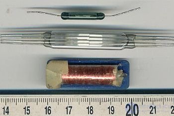
Reed switch with electromagnetic coil is a reed switch.
There are varieties of reed switches in the contact group: with a closing contact, an opening contact and a switching contact.
Reed switch with closing contact - the contact is open in the absence of a magnetic field, and closes in the presence of a magnetic field.
Reed switch with opener contact - the contact is closed in the absence of a magnetic field, and opens in the presence of a magnetic field.
A reed switch with a switching contact has three leads — in the absence of a magnetic field, one pair of leads is closed, and in the presence of a magnetic field, another pair is closed.
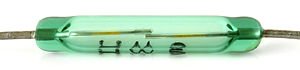
Reed switches are also distinguished by design features. They are dry (with dry contacts) and mercury, in which a drop of mercury wets the contacting surfaces, reducing their electrical resistance and preventing the plates from vibrating during operation.
The difference between the reed switch and the Hall sensor:
The main trend is the replacement of reed switches with solid Hall sensors.
It is believed that the first reed switch was developed by the scientist of the Leningrad Electrotechnical University S. Ulitovskiy in 1938, but because of the lack of demand for this invention, it did not become widely known and was not patented. [3]
The need for the production of reed switches appeared in the USSR in the 1960s in connection with the mass telephonization of the country. The use of reed switches was associated with the wide distribution of automatic telephone exchanges and other high-precision equipment necessary for their operation. [four]
In the mid-1960s, the forecasts of the research institutes of the USSR Ministry of Communications provided a justification for the use of reed switches as switching elements and service relays of matrix fields of automatic telephone exchanges. Such conclusions were confirmed by the development of the production of reed switches for these purposes in the United States, beginning in the mid-50s.
The Ryazan metal-ceramic factory, previously engaged exclusively in the production of metal-ceramic microwave lamps, was chosen as the site for the production and development of reed switches. By order of the USSR Electronic Industry Minister No. 161С of November 25, 1966, the plant was instructed to organize specialized production of reed switches in 1966‒67. The planned targets for the plant for the production of cermet lamps were reduced. The annual output of reed switches was prescribed to bring to 25 million pieces by 1975. [five]
At present, Ryazan Metal-Ceramic Instruments Plant OJSC continues to be the only reed switch company in Russia and the CIS countries. For 2013, the plant occupies 15% of the global reed switch market. Over the entire period of the plant's existence, 3.5 billion units were produced. [6] [7]
At the time of switching the electrical circuit transients occur. This is due to the so-called "bounce" of the contact system and entails distortion of the useful signal, manifesting itself in the form of "emissions" and "subsidence" of the switched voltage. As a result, damage to both the equipment located on the switched line and the switching contact group is possible. This effect is especially pronounced when switching high-current circuits and, to a lesser extent, circuits with a current load of more than 1 A. Electric erosion and wear of the contact system result in this effect, which is exacerbated when using designs of "open" contact groups of relays, contactors and starters operated in an aggressive environment.
Another problem is the switching of low-power signals. In this case, the transition resistance at the point of contact may be so noticeable that it will lead to a significant weakening of the signal or to its complete loss. This is manifested due to the oxidation and self-passivation of contact group materials. These chemical processes are almost impossible to avoid in unsealed cases of electromagnetic system relays.
When using semiconductor controlled switching elements, it is necessary to take into account the resistance of the structure and its nonlinearity when switching low-power signals, as well as the presence of leakage currents, which imposes a restriction on their use in areas where high electrical safety is required when switching high voltages.
In automation systems, it is often necessary to provide a galvanic isolation between the digital part, connected by various bus interfaces with a processor, sensitive to different leads and influences from the power and switching devices, and the power part, which is under high potential relative to the common wire.
The main requirement here is also to ensure electrical safety, high speed of operation and miniature switching devices. The size of the switching element is an important factor due to the frequent need to provide galvanic isolation of a relatively large number of external input-output lines - from several tens to several hundred.
One of the solutions to the tasks is the use of sealed magnetically controlled contact groups, "reed switches", combined with a coil in a design known as a "reed switch".
Reed relays were first invented at Bell Labs in early 1930s. However, it was not until 1940 that they began to be widely used as sensors and for their intended purpose. They began to be used as serial switches for early electronic and test equipment. At the end of 1940, Western Electric began using reed relays in the telephone station of its central office, where they are still used today. Reed relays have played a huge role in the development of telecommunication technologies.
For several years, various reed switch manufacturers appeared and disappeared, some of them held their positions longer than the low quality of the products and their unreliability allowed. However, the majority of modern manufacturers of reed relays create high-quality products with very good reliability indicators. This provides an unprecedented opportunity for their sales growth.
In modern production technologies, reed relays are used in all market segments, including test and measuring equipment, medical electronics, telecommunications equipment, automation, security systems and others. There is an increase in consumption, world production of reed relays cannot satisfy the growing need for them.
Reed relays are unique in their technology. Being airtight, they can be used in virtually any environmental conditions. Very simple in their design, they combine a variety of manufacturing technologies. A critical indicator of quality and reliability is tightness at the point of contact between the case glass and the contact terminal metal. These materials must have a strictly identical temperature coefficient of linear expansion. Otherwise, cracking and poor bulb tightness are possible. Regardless of the technology of sputtering or electroplating, the process of applying contact materials (usually rhodium or ruthenium) requires compliance with high accuracy and high purity of industrial premises, which are similar in their requirements to semiconductor production. Similarly to the production of semiconductors, any foreign particles present during production will lead to an increase in losses, a decrease in the quality and reliability of products.
Over time, the reed relays have decreased in size from approximately 50 to 6 mm. Reducing the size allowed to extend their use, in particular, to the devices of the RF range and high-speed devices.
Single magnetically controlled contacts are widely used primarily as sensors sensitive to an external magnetic field.
The reed switch consists of two ferromagnetic plates, usually made of steel and nickel, sealed in a glass capsule. Plates are placed so that they overlap, providing a small air gap, and close in the presence of a magnetic field of an appropriate force. The contact area of both plates has a sprayed or electroplated coating made of a very resistant metal (usually rhodium, ruthenium). The structure of the contact coating layers is shown in Figures 2 and 3 for rhodium and iridium, respectively.
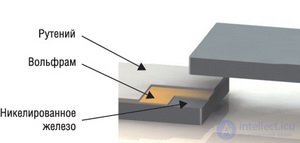
Fig. 2. The structure of the contact group NiFe-W-Ru

Fig. 3. Structure of the contact group NiFe-Au-Ro-Ir
Iridium and rhodium are very resistant to erosion metals. They make it possible to ensure a long contact time if they do not commute a very powerful load. The capsule cavity usually contains nitrogen or a similar inert gas. Some types of reed switches are evacuated to increase the potential of the switched voltage. Reed switch plates behave like a magnetic circuit: when an external magnetic field is applied from a magnet or an electromagnetic coil, mutual attraction of the plates occurs. The fields created with the opposite sign ensure the closure of the contacts when the magnetic force exceeds the return force of the contact plates. When the force of the external magnetic field decreases, so that the force between the contacts becomes less than the return force, the contact opens.
The reed switch described above and shown in Figure 1 is characterized as 1 Form A (normally open or unipolar unidirectional SPST-group of contacts).
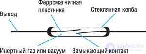
Fig. 1. The device of the simplest reed switch with type A contact group (normally open contacts)
Multi-directional switches of this configuration are described as 2 Form A (two normally open contacts or a bipolar DPST unidirectional relay), a 3 Form A relay has three normally open contacts, and so on. A normally closed contact is described as 1 Form B. A relay with a switching contact is shown in Figure 4 and is characterized as unidirectional bidirectional (SPDT) 1 Form C.
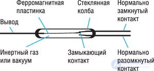
Fig. 4. The device of the three-output reed switch type 1 Form С (unipolar bidirectional)
The main types of contact groups used in both reed switches and reed relays are listed in Table 1.
Table 1. The main types of contact groups of reed switches and reed relays
| Name, type of contact group | The electrical circuit of the contact group * |
|---|---|
| 1 Form A |  |
| 1 Form B |  |
| 1 Form C |  |
| 3 Form A | 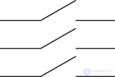 |
| * - Other combinations of the number and type of contact groups in reed relays are possible. However, for single reed switches, only single contact groups of 1 Form A, 1 Form B or 1 Form C are used. | |
The common plate is the only moving part of the reed switch of this type; it is closed with a normally closed relay contact in the absence of a magnetic field. When a magnetic field of a corresponding force occurs, the common contact is closed with a normally open contact. Both plates are normally open and normally closed contacts are fixed. All three plates have a ferromagnetic coating, but the contact area of a normally closed contact is made of a nonmagnetic material welded to the ferromagnetic plate. When placed in a magnetic field, both terminals take the same polarization opposite to the moving contact. Non-magnetic material interrupts the magnetic flux in a normally closed contact, and the moving contact is attracted to a normally open contact, forming with it a continuous magnetic circuit for magnetic flux.
The operation of the magnetic contact can be achieved in two ways:
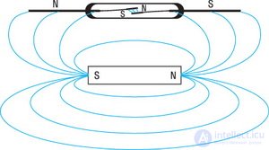
Fig. 5. Принцип работы магнитоуправляемого контакта – геркона
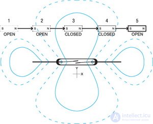
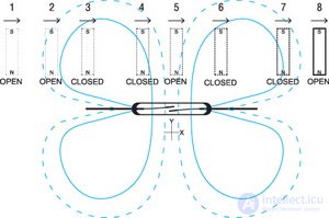
Fig. 6. Взаимодействие постоянного магнита с магнитоуправляемым контактом: а) параллельная ориентация постоянного магнита, б) перпендикулярная ориентация постоянного магнита
Когда постоянный магнит приближается к магнитоуправляемой группе контактов, каждая пластина намагничивается. При этом возникает сила их взаимного притяжения. При достижении силой магнитного поля порогового значения, превышающего упругость пластин контактов, они замыкаются. При исчезновении внешнего магнитного поля, остаточное магнитное поле в ферромагнитных пластинах контактов также рассеивается, вызывая их размыкание. При наличии остаточного магнитного поля на пластинах контактов, характеристики геркона будут отличны от заложенных при производстве. Поэтому при их изготовлении применяют высокотемпературный отжиг, чтобы снять остаточное магнитное поле.
Магнитная характеристика контактной группы магнитоуправляемых контактов имеет выраженную анизотропную симметричную направленность. На рисунке 6 изображен вид диаграммы взаимодействия постоянного магнита с магнитоуправляемым контактом, «герконом».
Рассмотрим это взаимодействие подробнее.
Поскольку контакты геркона обладают своей диаграммой чувствительности, то, в зависимости от расположения магнита и его ориентации в пространстве относительно контактной группы, возможны три варианта взаимодействия:
На рисунке 6 сплошными линиями показана зона уверенного срабатывания контактной группы. При нахождении постоянного магнита в ее пределах магнитное поле является достаточным для надежного срабатывания контактной группы. Пунктиром показана зона гистерезиса – при вхождении магнита в эту зону магнитное поле еще недостаточно сильно для срабатывания контактной группы, но его еще достаточно для удержания в «сработавшем» состоянии контактной группы. В случае иной конфигурации контактной группы геркона, отличной от рассматриваемой 1 Form A, под «срабатыванием» будет пониматься размыкание группы 1 Form B или переключение 1 Form C. Причем диаграмма чувствительности различна для параллельной (рисунок 6а) и перпендикулярной (рисунок 6б) ориентации постоянного магнита-активатора относительно контактной группы геркона.
На основе этого принципа работы магнитоуправляемой герметичной контактной группы можно привести несколько способов управления герконом, представленных на рисунке 7.
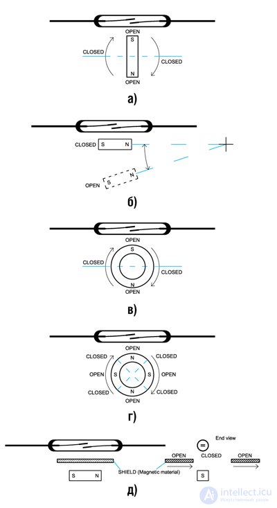
Fig. 7. Способы управления магнитоуправляемым контактом
На рисунке 7а, в, г изображены способы управления контактной группой геркона посредством вращающегося постоянного магнита, причем число срабатываний на один оборот такого активатора будет определяться количеством полюсов магнита-активатора.
На рисунке 7б приведен способ углового перемещения постоянного магнита-активатора.
На рисунке 7д магнит неподвижен – перемещается шторка, экранирующая магнитное поле активатора – постоянного магнита.
Основные типы герконов, выпускаемые компанией Standex-Meder Electroincs, приведены в таблице 2.
Таблица 2. Основные типы одиночных герконов
| Name | Внешний вид и габариты, мм | Рассеиваемая мощность, Вт |
Коммутируемое напряжение, В |
Коммутируемый ток, А | Application |
|---|---|---|---|---|---|
| KSK-1A35 | 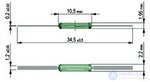 |
0…20 | 0…200 | 0…1 | Общее, автомобильная аппаратура |
| KSK-1A46 | 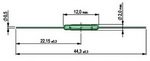 |
0…10 | 0…200 | 0…0,5 | КИП |
| KSK-1A66 | 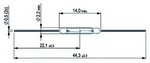 |
0…10 | 0…200 | 0…0,5 | Общее, автомобильная аппаратура |
| KSK-1A87 | 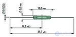 |
0…10 | 0…200 | 0…0,5 | Общее, автомобильная аппаратура, КИП |
При применении одиночных герконов следует помнить, что значительное превышение допустимого коммутируемого тока через контакты может привести к их самопроизвольному размыканию, подгоранию и, как следствие, выходу геркона из строя. Это также относится и к рассматриваемым далее герконовым реле на основе магнитоуправляемых контактов.
Магнитное поле, управляющее контактной группой геркона, может быть создано также соленоидом – катушкой, образующей единый конструктив с герметизированной магнитоуправляемой контактной группой, либо несколькими контактными группами, размещенными в одном корпусе. Принцип работы приведен на рисунке 8. Магнитоуправляемый контакт, помещенный внутрь соленоида, где наиболее сильное магнитное поле сосредоточено в центре, образует герконовое реле. При возникновении магнитного поля происходит поляризация пластин, вызывающая их взаимное притяжение, и, соответственно, замыкание нормально разомкнутого контакта.
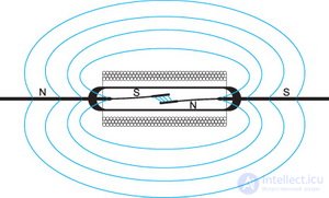
Fig. 8. Принцип работы герконового реле
При использовании соответствующей конструкции, материалов и размещении электростатического экрана между колбой и катушкой герконового реле, можно добиться его способности коммутировать сигналы очень малой мощности (порядка нВ или фА) без потери полезной составляющей или с минимальным ослаблением. Достижение таких характеристик другими способами в настоящее время невозможно без значительного повышения цены конечного изделия. Конструкция такого реле приведена на рисунке 9.
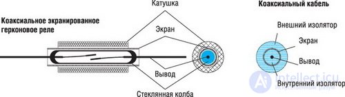
Fig. 9. Разрез герконового реле: катушка, герметичный контакт и размещение экрана (коаксиала)
При использовании коаксиального экрана герконовое реле становится таким же, как и линия передачи для высокочастотного сигнала. С уменьшением размера герконовых реле общий габарит корпуса стал менее 8 мм, уменьшая распределенную емкость контакта по отношению к экрану до менее чем 0,8 пФ. Это позволяет герконовым реле коммутировать сигналы с частотой вплоть до 6 ГГц без значительных потерь мощности сигнала (ослабление составит 3 дБ). В настоящее время достижимы вносимые потери на уровне 0,2 дБ в диапазоне 1,1…2 ГГц. Частотные характеристики герконовых реле превосходят современные арсенид-галлиевые высокочастотные КМОП-структуры и являются вполне конкурентоспособными при работе на частотах от 1 ГГц и выше. В настоящее время герконовые реле широко используются в тестовом оборудовании и оборудовании сотовых телекоммуникаций благодаря их превосходным частотным характеристикам.
Помимо герконовых реле, в категорию коммутационной аппаратуры входят также электромеханические и так называемые «твердотельные», полупроводниковые реле. Невозможно указать единственное оптимальное решение для всех случаев применения; выбор того или иного варианта остается за разработчиком. В таблице 3 приведены отличия герконовых реле от электромеханических и полупроводниковых. Это позволит выбрать желаемое решение, исходя из требуемых параметров окружающей среды и условий коммутации.
Таблица 3. Характеристики герконовых реле в сравнении с электромеханическими и полупроводниковыми
| Characteristic | Герконовое реле | Электромеханическое реле | Полупроводниковое реле |
|---|---|---|---|
| Время переключения, мс | 0,1…1 | Более 5 | Менее 0,1 |
| Средний срок службы | 1010 циклов | 106 циклов | Приближается к бесконечности |
| Power consumption, mV | 3 | 50 | 3 |
| Maximum switching voltage, kV DC | ten | 1.5 | 1.5 |
| Maximum switched current, A | 3 | Up to 40 | Up to 40 |
| Minimum load, mW | Unlimited (µV, pA) | 50 | 50 |
| Insulation resistance, Ohm | 1014 | 109 | 109 |
| Noise | Missing | Switching interference | Very tall |
| Insertion loss, dB | 0.5 | 0.5 | 2 |
| Overload sensitivity | High (open) | Insensitive | Failure (breakdown) |
| Other | Linear characteristic from DC up to GHz range | Linear characteristic from DC up to GHz range | Switched signal distortion |
| Galvanic isolation (air gap) | Galvanic isolation (air gap) | No galvanic isolation between high-voltage and low-voltage parts |
The company Standex-Meder Electronics is one of the well-known manufacturers of electronics, in particular, sealed contacts, reed relays and sensors containing magnetically controlled components.
Since 1987, the company has produced a huge amount of electronic components. Technological control allows you to provide an unprecedented level of product quality. The company's products are widely used in various industries: aerospace and medical industries, telecommunications systems. Let's get acquainted with the most widely used series of relays.
The BE series is available in sealed plastic or metal cases. These relays have a pin layout that is compatible with most relays manufactured by other global manufacturers.
The DIL series is used when it is necessary to provide a high breakdown voltage between the terminals (up to 4250 V).
The DIP series is general purpose, compatible with all relays of this form factor from other manufacturers.
The MS series differs by half the occupied area (only half of the area occupied by a conventional relay). They are used as voltage relays. This series also has an RF performance capable of switching signals up to 1 GHz. Relays are used in instrumentation and test equipment.
NP series relay is a miniature relay with a large set of contact groups with dimensions of only 10.1x22 mm.
Relays of the SIL series occupy only half the space occupied by the relays of the DIP or DIL series on the printed circuit board, providing all the advantages of hermetic signal switching.
UMS series relays are the smallest, taking up only a quarter of the MS series relay seat. They have characteristics similar to the larger “SIL” series. The coil of these relays already contains a protective diode, and the internal shielding allows placing the relays in groups, which is important for use in switching arrays of instrumentation and telecommunication systems.
The list of subminiature relays, their appearance and basic parameters are given in Table 4.
Table 4. Key parameters and comparative characteristics of the Standex-Meder subminiature relay
| Parameter | BE series | DIL Series | DIP Series | MS Series | NP series | SIL series | UMS Series |
|---|---|---|---|---|---|---|---|
| Appearance and dimensions |  |
 |
 |
 |
 |
 |
 |
| Coil voltage, V | 5 ... 48 | 5 ... 24 | 3 ... 24 | 5 ... 12 | 4… 24 | 3 ... 24 | 5 ... 12 |
| Coil resistance, Ohm | 30 ... 12000 | 200 ... 11000 | 200 ... 2000 | 280 ... 700 | 500 ... 10,000 | 20 ... 2000 | 280 ... 700 |
| Contact groups | 1 or 2 (A, B, C) (E); 3A, 4A, 5A | 1A, 1C, 2A, 2C | 1A, 1B, 1C, 2A | 1A, 2A, 1B | 1A, 1C, 2A | 1A, 1B, 1C | 1A |
| Rated power, W | 0 ... 100 | 0 ... 50 | 0 ... 50 | 0 ... 10 | 0 ... 15 | 0 ... 50 | ten |
| Switched voltage, V | 0 ... 1000 | 0 ... 500 | 0 ... 500 | 0 ... 200 | 0 ... 500 | 0 ... 500 | 170 |
| Switched current, A | 0 ... 1.0 | 0 ... 2.0 | 0 ... 2.0 | 0 ... 0.5 | 0 ... 1.0 | 0 ... 2.0 | 0.5 |
| Maximum allowed current through relay, A | 2.5 | 2.0 | 2.0 | 2.0 | 1.25 | 2.0 | 1.0 |
| Electric voltage breakdown, V |
Over 4000 | 250 ... 1500 | 250 ... 1500 | 1500 | 1500 | 200 ... 1500 | - |
When using reed relays, you should be guided by the following:
Sealed relays have several advantages over other types of relays, the most important of which is the lack of influence on the switched signal in a wide frequency range and good isolation between the switched and control circuits. A wide range of reed relays and their high reliability with small sizes allow them to occupy an extensive niche of the modern electronics market and to find application in promising developments of instrumentation and industrial equipment in various industries.
Single magnetically controlled hermetic contact groups are widely used as various sensors based on the interaction of the contact group of a reed switch and an external magnet.

Comments
To leave a comment
Sensors
Terms: Sensors