Lecture

Photoresistor
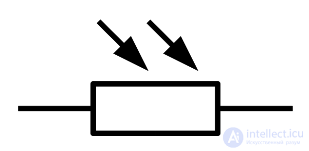
Electrical photoresistor designation
A photoresistor is a sensor whose electrical resistance varies depending on the intensity of the light falling on it. The more intense the light, the more free charge carriers are created and the less the resistance of the element becomes. Two external metal contacts of the photoresistor go through the ceramic base material to the photosensitive film, which by its geometry and material property determines the electrical properties of resistance. Since the photosensitive material is in nature with high resistance, between the electrodes with a thin winding path, with an average light intensity, a low total resistance of the element is obtained. Just like the human eye, a photoresistor is sensitive to a specific wavelength range of light. When choosing a photocell, you have to reckon with this, because otherwise it may not respond at all to the light source used in the application. Here are the wavelengths of visible light, simplifiedly divided by color.
| Colour | Wavelength Range (nm) |
|---|---|
| Violet | 400 - 450 |
| Blue | 450-500 |
| Green | 500 - 570 |
| Yellow | 570 - 590 |
| Orange | 590 - 610 |
| Red | 610 - 700 |
At photoresistors the temperature range is also determined. If you use the sensor at different temperatures, then you should definitely enter clarifying transformations, because resistance property depends on the outside temperature.
To characterize the intensity of light, the physical quantity illuminance (symbol E) is used, which indicates the amount of luminous flux reaching a surface. To measure the unit, there is a lux (lux), where 1 lux means that a luminous flux of 1 lumen (lm) uniformly falls on a surface of 1 m2. In real life, light almost never falls on a (residential) surface evenly, and therefore the illumination is obtained more on average. For comparison, some examples of illumination are given:
| Environment | Illumination (lx) |
|---|---|
| Full moon | 0.1 |
| Dusk | one |
| Lecture hall | ten |
| Class | thirty |
| Dawn or dusk | 400 |
| Hospital operating room | 500 - 1000 |
| Direct sunlight | 10,000 |
The board of the “Sensors” module of the Home Lab is equipped with a VT935G photoresistor. One of its outputs is connected to the power supply of +5 V and the other to channel 1 (PF1 output) of the analog-digital converter of the microcontroller. The same 10 kΩ resistor is connected to the same output of the microcontroller and the ground, which together with the photoresistor forms a voltage divider. Since the electrical resistance of the photoresistor decreases with increasing intensity of the light incident on it, the measured voltage at the microcontroller output increases with increasing light intensity. It is important to note that the photoresistor used in the Home Lab reacts more intensely to the yellow and orange light.
The VT935G sensor is not a measuring device for a specific purpose, but serves more to indicate general light conditions - for example, whether the lamp is lit in the room or not. Therefore, you just need to measure the resistance of the sensor in a semi-dark room, write it into the program and use it to compare the measurements - lighter or darker.
This task is a little more difficult, because Illumination is sought in suites. An approximate formula and floating-point numbers are used to create this. Floating-point numbers in C are float and double types that can represent fractional numbers. Their disadvantage is a rather large need for resources. Computers have special hardware for computing them, for an 8-bit AVR microcontroller, calculations are done in software, which takes quite a lot of software memory and time. If the drawbacks are unimportant, then the floating point numbers should be used.
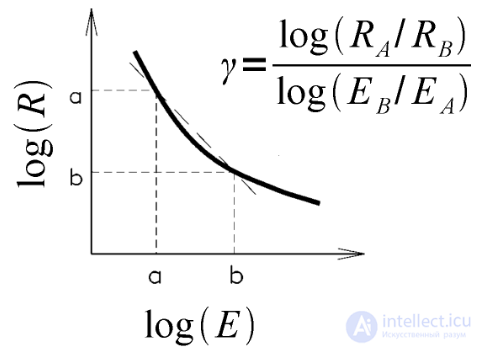
The relationship between illumination (E) and electrical resistance (R) VT935G
About the relationship between illumination and electrical resistance of the photoresistor gives an approximate formula in the specification of the sensor. As can be seen in the graph above, on a logarithmic scale, the luminance and resistance are approximately linearly dependent and form a direct equation, because the following transformation is applied:
log (a / b) = log (a) - log (b)
The link characterizes the γ factor (smooth lift), which at the VT935G sensor is 0.9. The data of one point of the line are also known: 18.5 kΩ resistance (RA) 1 at 10 lx illumination (EA). Thus, there are 1 point coordinates and a smooth lift, and only one coordinate is enough to calculate any other point. If you measure the resistance of the sensor (RB), then you can calculate the illumination (EB) incident on the sensor from the line equation. Express the EB line equation:
log (EB) = log (RA / RB) / γ + log (EA)
EB = 10log (RA / RB) / γ + log (EA)
Thus, there is a formula for calculating the illumination if resistance is known. It is impossible to measure the resistance directly by the microcontroller - for this, the photoresistor is located in the voltage divider, the output voltage of which converts the analog-digital converter to specific numbers (ADC). To find the resistance, first we need to calculate the output voltage (U2), the voltage divider, from the ADC value, taking into account the compared voltage (Uref) of the converter. The formula is as follows:
U2 = Uref ⋅ (ADC / 1024)
From the formula of the voltage divider (see the chapter of the voltage divider) you can find the resistance (R1) in the top photoresistor circuit:
R1 = (R2 ⋅ U1) / U2 - R2
Further, when calculating the voltage and resistance, the known factors are replaced by the values and the lower indices are omitted:
U = 5 (ADC / 1024)
R = (10 ⋅ 5) / U - 10
To find the light can make simplifying translations:
E = 10log (18.5 / R) / 0.9 + 1 = 10log (18.5 / R) 10/9 101 =
= 10log18.5 10/9 - logR 10/9 ⋅ 10 = (10log18.5 10/9 / 10logR ⋅ 10/9) ⋅ 10 =
= (18.510 / 9 / R10 / 9) ⋅ 10 = 18.510 / 9 10 ⋅ R-10/9
By calculating the constant before the variable R, the formula remains as follows:
E = 255.84 ⋅ R-10/9
Using these formulas, you can only use a photoresistor located on the board of the Sensors module of the Home Laboratory. When using a circuit with other components, the corresponding numerical values will have to be changed in the formulas. The following is the source code of the sample program that measures the ADC, calculates and displays the illumination on the LCD screen. But even before compiling the program, the project should make settings for using floating-point numbers. There is a quick guide for this in the chapter on software installation.
In the example program, variable voltages, resistances, and luminance are indicated by a floating-point number of double type. Numbers that are used in a floating-point action should always contain a number after the comma (in the C language of the dot), this number can be zero, because in this case the compiler understands them correctly. With the help of sprintf, when converting floating-point numbers into text, you need to use the format “% f“, which can be supplemented with whole and fractional numbers, for example “% 3.2“, which always shows 3 full numbers and 2 decimal places.
 //
 // Example of the photoresistor program of the module “Sensors” of the Home Laboratory.
 // The approximate illumination in lux is displayed on the LCD screen.
 //
 #include
 #include
 #include
 #include
 #include

 //
 // Main program
 //
 int main (void)
 {
	 char text [16];
	 unsigned short adc_value;
	 double voltage, resistance, illuminance;

	 // Setting the LCD screen
	 lcd_alpha_init (LCD_ALPHA_DISP_ON);

	 // Clear LCD Screen
	 lcd_alpha_clear ();

	 // The name of the program
	 lcd_alpha_write_string ("Light meter");

	 // Configure the ADC converter
	 adc_init (ADC_REF_AVCC, ADC_PRESCALE_8);

	 // Endless cycle
	 while (true)
	 {
		 // Reading the averaged value of the photoresistor
		 adc_value = adc_get_average_value (1, 10);

		 // Calculate the voltage at the ADC input
		 voltage = 5.0 * ((double) adc_value / 1024.0);

		 // Measurement of photoresistor resistance in voltage divider
		 resistance = (10.0 * 5.0) / voltage - 10.0;

		 // Calculate the illumination in suites
		 illuminance = 255.84 * pow (resistance, -10/9);

		 // Translating Illumination To Text
		 sprintf (text, "% 0.1f lux", illuminance);

		 // Display readings on LCD
		 lcd_alpha_goto_xy (0, 1);
		 lcd_alpha_write_string (text);

		 // 500 ms latency
		 sw_delay_ms (500);
	 }
 }

Comments
To leave a comment
Sensors
Terms: Sensors