Lecture

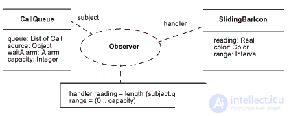
On the cooperation diagram, rectangles depict objects participating in an interaction, containing the name of the object, its class and, possibly, attribute values. As in the class diagram, the associations between objects are indicated in the form of various connecting lines. In this case, you can explicitly specify the names of the associations and the roles played by the objects in this association.
In contrast to the sequence diagram, only relations between objects that play certain roles in the interaction are depicted in the cooperation diagram.
The main feature of the diagram of cooperation is the ability to graphically represent not only the sequence of interaction, but also all the structural relations between the objects participating in this interaction.
First of all, in the cooperation diagram, rectangular objects depict the objects participating in the interaction, containing the name of the object, its class and, possibly, attribute values. Further, as in the class diagram, the associations between the objects are indicated in the form of various connecting lines. In this case, you can explicitly specify the names of the associations and the roles played by the objects in this association. Additionally, dynamic links — message flows — can be depicted. They are also represented in the form of connecting lines between the objects, above which is located an arrow indicating the direction, the name of the message and the sequence number in the overall sequence of message initialization.
In contrast to the sequence diagram, only relations between objects that play certain roles in the interaction are depicted in the cooperation diagram. This chart does not indicate time as a separate measurement. Therefore, the sequence of interactions and parallel threads can be determined using sequence numbers. Therefore, if it is necessary to explicitly specify the relationships between objects in real time, it is better to do this in the sequence diagram.
Cooperation
The concept of collaboration (collaboration) is one of the fundamental concepts in UML. It serves to designate the set of objects interacting with a specific goal in the general context of the simulated system. The goal of the cooperation itself is to specify the features of the implementation of individual most significant operations in the system. Cooperation defines the structure of the system behavior in terms of the interaction of participants in this cooperation.
Cooperation can be presented at two levels:
- specification level — shows the roles of classifiers and the role of associations in the interaction under consideration;
- example level - indicates instances and relationships that form separate roles in cooperation.
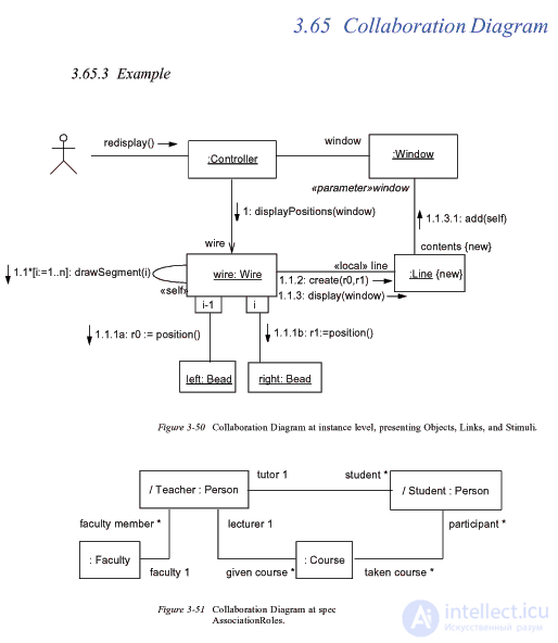
The specification level collaboration diagram shows the roles that the elements involved in the interaction play. The elements of cooperation at this level are classes and associations, which designate the separate roles of classifiers and associations between the participants of cooperation.
An example level cooperation diagram is represented by a collection of objects (instances of classes) and relationships (instances of associations). At the same time communications are supplemented with message arrows. At this level, only objects that are directly related to the implementation of the operation or classifier are shown. At the same time, it is not at all necessary to depict all properties or all associations, since only the roles of classifiers are present in the cooperation diagram, but not the classifiers themselves. Thus, while the classifier requires a complete description of all its instances, the role of the classifier requires the description of only those properties and associations that are necessary for participation in a separate cooperation.
This implies an important consequence. The same set of objects can participate in various cooperations. Depending on the cooperation in question, both the properties of individual objects and the relationships between them can change. This is what distinguishes the cooperation diagram from the class diagram in which all properties and associations between the elements of the diagram should be indicated.
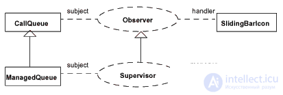
The specification-level cooperation is depicted in the diagram as a dotted ellipse, inside which the name of this cooperation is recorded. This view of cooperation relates to a separate use case and details the features of its subsequent implementation. The symbol of the cooperation ellipse is connected by segments of the dotted line with each of the participants of this cooperation, which can be objects or classes. Each of these dashed lines is marked with a participant’s role. Roles correspond to the names of the elements in the context of the whole cooperation. These names are interpreted as parameters that limit the specification of elements for any appearance in separate model representations.
A simple class in a cooperation diagram is indicated by a class rectangle within which a line of text is written. This line of text is called the classifier role. The role of the classifier shows the peculiarity of using objects of this class. Usually only a section of the class name is shown in a rectangle, although the possibility of specifying sections of attributes and operations is not excluded.
A line of text in a rectangle should have the following format:
'/' <Classifier role name> ':' <Classifier name>
[':' <Classifier Name>] *
Here the classifier name, if necessary, may include the full path of all nested packages. In this case, one packet from the other is separated by a double colon " :: ". In some cases, it can be limited to indicating only the closest package to which this cooperation belongs. The symbol "*" is used to indicate the possibility of iteratively repeating the name of the classifier.
If cooperation allows a generalized representation, then the diagrams can indicate the generalization of the corresponding elements. This method can be used to identify individual cooperatives that are a special case or specialization of another cooperation. Such a situation is depicted by the usual generalization arrow, directed from the symbol of a subsidiary cooperation to the symbol of ancestral cooperation. The roles of subsidiary cooperatives may be specializations of the roles of ancestral cooperatives.
In some cases, it is necessary to clearly indicate the fact that cooperation is the implementation of a certain operation or classifier. This can be represented in one of two ways.
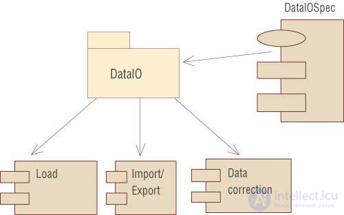
First, you can connect the cooperation symbol with a dashed line with an arrow of generalization with the class symbol, the operation of which is specified by this cooperation.
Secondly, you can simply portray the symbol of cooperation, within which you can specify all the necessary information recorded according to certain rules. These rules define the format of the name of the collaboration, followed by the colon and the name of the class. The class name is followed by a double colon and the name of the operation.
Such a general idea of cooperation at the specification level is used in the initial design stages. In the following, each of the cooperatives is subject to detail at the level of examples, which reveals the content and structure of the interrelationships of its elements in a separate cooperation diagram. In this case, the elements of a cooperation diagram are objects and links, supplemented by messages.
As noted above, the object (object) is a separate instance of the class that is created at the stage of program execution. It can have its own name and specific attribute values. In relation to objects, the formatting string format is supplemented with the object name and takes the following form (the whole record is underlined):
<Object name> '/' <Classifier role name> ':' <Classifier name>
[':' <Classifier Name>] *
The name of a role can be omitted if there is only one role in cooperation that can be played by objects created on the basis of this class.
Thus, to designate the role of a classifier, it is sufficient to specify either the class name (along with a colon) or the name of the role (along with a slash). Otherwise, the rectangle will correspond to the normal class. If the role that the object should play is inherited from several classes, then all of them should be specified explicitly and separated by a comma and a colon.
Below are possible options for writing a string of text in the object's rectangle:
: C is an anonymous object formed on the basis of class C;
/ R - an anonymous object that plays the role of R;
/ R: C - an anonymous object formed on the basis of class C and playing the role of R;
O / R - an object named O, playing the role of R;
O: C - an object with the name O, formed on the basis of the class C;
O / R: C - an object with the name O, formed on the basis of class C and playing the role of R;
O or - object with the name O;
O: - “orphan object” with the name O;
/ R - the role named R;
: C - anonymous role based on class C;
/ R: C - a role named R based on class C.
A multiobject is a multitude of objects at one of the ends of an association. In the cooperation diagram, a multi-object is used to show operations and signals that are addressed to the whole set of objects, and not just one. A multiobject is represented by two rectangles, one of which stands for the right top vertex of the other. The message arrow refers to the entire set of objects that denote this multi-object. The relationship chart can clearly indicate the composition relationship between a multi-object and an individual object from its set.
In the context of the UML language, all objects are divided into two categories: passive and active .
The passive object operates only with data and cannot initiate the activity of controlling other objects. However, passive objects can send signals during the execution of requests that they receive.
The active object has its own control thread and can initiate activities to control other objects. By thread here is meant some lightweight control flow that can run in parallel with other computational threads or control threads within one computational process or control process.
Active objects on canonical diagrams are indicated by a rectangle with wider borders. Sometimes the keyword {active} can be explicitly specified to highlight the active object in the diagram. Each active object can initiate a single thread or control process and represent the starting point of the control flow.
A composite object or a container object is intended to represent an object that has its own structure and internal threads (threads) of control. A composite object is an instance of a composite class (container class) that is related by an aggregation or composition relationship with its parts. Similar relationships link together the corresponding objects.
In the cooperation diagrams, the compound object is depicted as a normal object consisting of two sections: the top and bottom. In the upper section, the name of the composite object is recorded, and in the lower section, instead of a list of attributes, its components. It is also allowed to have other composite objects as components.
A link is an instance or example of an arbitrary association. Communication as an element of the UML language can take place between two or more objects. The binary connection in the cooperation diagram is represented by a straight line segment connecting two rectangles of objects. At each end of this line, the names of the roles of this association can be explicitly indicated. Next to the line in its middle part can be written the name of the corresponding association.
Relationships do not have proper names, since they are completely identical as instances of an association. In other words, all links in a cooperation diagram can only be anonymous and are written without a colon before the name of the association. For relationships, the multiplicity is also not indicated. However, other designations of special cases of association (aggregation, composition) may be present at individual ends of bonds.
A connection may have some stereotypes that are written next to one of its ends and indicate the peculiarity of the implementation of this connection. The following stereotypes can be used in UML for this purpose:
- “Association” is an association (assumed by default, therefore this stereotype can be omitted);
- “Parameter” is a method parameter. The corresponding object can only be a parameter of a certain method;
- "Local" is a local method variable. Its scope is limited to the neighboring object;
- “Global” is a global variable. Its scope extends to the whole diagram of cooperation;
- “Self” is a reflexive connection of an object with itself, which allows the object to transmit a message to itself. In the cooperation diagram, the reflexive relationship is represented by a loop in the upper part of the object's rectangle.
Messages
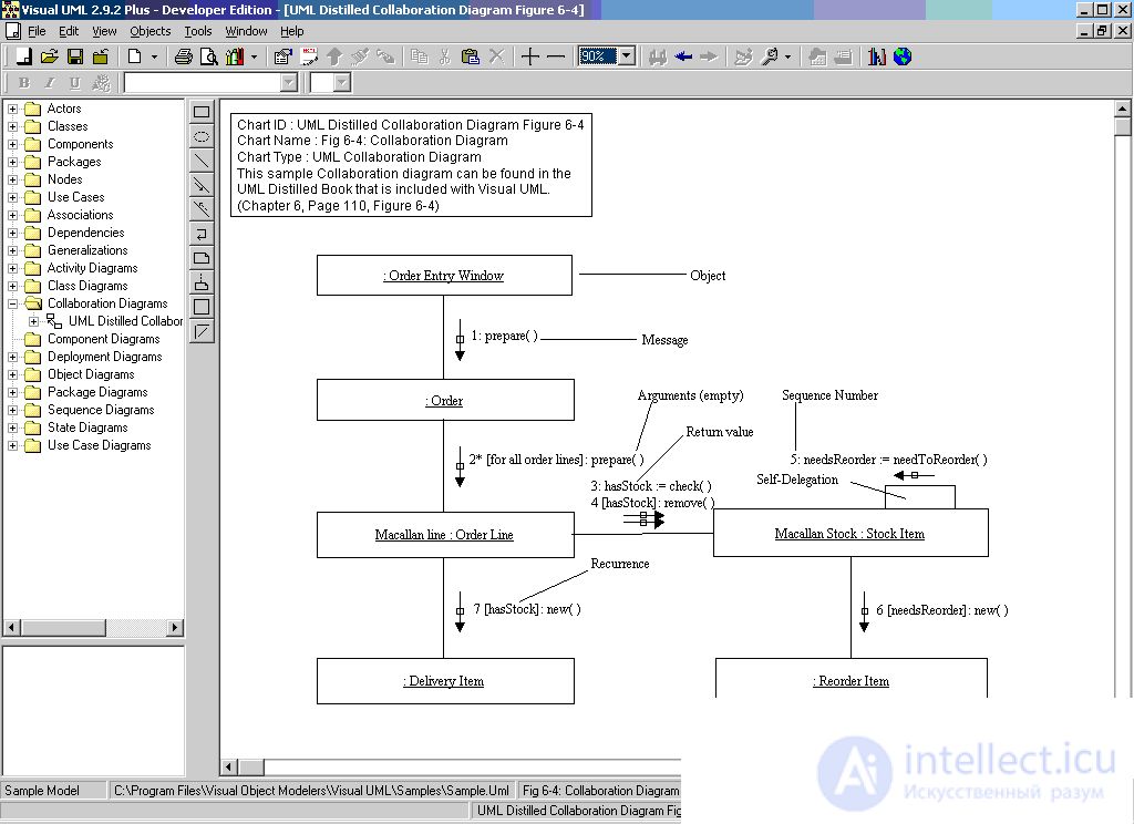
Messages , as elements of the UML language, have already been considered earlier when studying a sequence diagram. When building a cooperation diagram, they have some additional semantic features. The message on the collaboration diagram specifies the communication between two objects, one of which transmits some information to the other. In this case, the first object expects that after receiving the message by the second object, some action will follow. Thus, it is the message that is the cause or incentive for starting operations, sending signals, creating and destroying individual objects. The link provides a channel for the directed transfer of messages between objects from the source object to the recipient object.
Сообщения в языке UML также специфицируют роли, которые играют объекты отправитель и получатель сообщения. Сообщения на диаграмме кооперации изображаются помеченными стрелками рядом (выше или ниже) с соответствующей связью или ролью ассоциации. Направление стрелки указывает на получателя сообщения. Внешний вид стрелки сообщения имеет определенный смысл. На диаграммах кооперации может использоваться один из четырех типов стрелок для обозначения сообщений:
- cплошная линия с треугольной стрелкой обозначает вызов процедуры или другого вложенного потока управления. Может быть также использована совместно с параллельно активными объектами, когда один из них передает сигнал и ожидает, пока не закончится некоторая вложенная последовательность действий. Обычно все такие сообщения являются синхронными, то есть инициируемыми по завершении некоторой деятельности или при выполнении некоторого условия;
- сплошная линия с V-образной стрелкой обозначает простой поток управления. Каждая такая стрелка изображает один этап в последовательности потока управления. Обычно все такие сообщения являются асинхронными;
- сплошная линия с полустрелкой используется для обозначения асинхронного потока управления. Соответствующие сообщения формируются в произвольные, заранее не известные моменты времени, как правило, активными объектами. Обычно сообщения этого типа являются начальными в последовательности потока управления и чаще всего инициируются актерами;
- пунктирная линия с V-образной стрелкой обозначает возврат из вызова процедуры. Стрелки этого типа зачастую отсутствуют на диаграммах кооперации, поскольку неявно предполагается их существование после окончания процесса активизации некоторой деятельности.
Каждое сообщение может быть помечено строкой текста, которая имеет следующий формат:
< Предшествующие сообщения> < [Сторожевое условие] >
<Выражение последовательности>
<Возвращаемое значение— имя сообщения> <Список аргументов>
Предшествующие сообщения - это разделенные запятыми номера сообщений, записанные перед наклонной черточкой:
<Номер сообщения ','>< Номер сообщения,'> '/'
Если список номеров сообщений пуст, то вся запись, включая наклонную черту, опускается. Каждый номер сообщения может быть выражением последовательности без рекурсивных символов. Выражение должно определять номер другого сообщения в этой же последовательности.
Смысл указания предшествующих сообщений заключается в том, что данное сообщение не может быть передано, пока не будут переданы своим адресатам все сообщения, номера которых записаны в данном списке.
Пример записи предшествующих сообщений:
A3, В4/ С5: ошибка записи (сектор).
Сторожевое условие является обычным булевским выражением и предназначено для синхронизации отдельных нитей потока управления. Сторожевое условие записывается в квадратных скобках и может быть опущено, если оно отсутствует у данного сообщения. Семантика сторожевого условия обеспечивает передачу сообщения только в том случае, если это условие принимает значение «истина».
Пример записи сторожевых условий без номеров предшествующих сообщений:
- [(х>=0)&(х<=255)] 1.2: отобразить_на_экране_цвет(х);
- [количество цифр номера = 7] 3.1: набрать_телефонный_номер();
Выражение последовательности - это разделенный точками список отдельных термов последовательностей, после которого записывается двоеточие:
<Терм последовательности'.'><Терм последовательности'.'>':'
Каждый из термов представляет отдельный уровень процедурной вложенности в форме законченной итерации. Наиболее верхний уровень соответствует самому левому терму последовательности. Если все потоки управления параллельные, то вложенность отсутствует. Каждый из термов последовательности имеет следующий синтаксис:
[Целое число| Имя] [Символ рекуррентности].
Целое число указывает на порядковый номер сообщения в процедурной последовательности верхнего уровня. Сообщения, номера которых отличаются на единицу, следуют подряд один за другим.
Имя используется для спецификации параллельных нитей управления. Сообщения, которые отличаются только именем, являются параллельными на этом уровне вложенности. На одном уровне вложенности все нити управления эквивалентны в смысле приоритета передачи сообщений.
Символ рекуррентности используется для указания условного или итеративного выполнения. Семантика рекуррентности представляет ноль или больше сообщений, которые должны быть выполнены в зависимости от записанного условия. Возможны два случая записи рекуррентности:
- '*' '[' Предложение-итерация ']' для записи итеративного выполнения соответствующего выражения. Итерация представляет последовательность сообщений одного уровня вложенности. Предложение-итерация может быть опущено, если условия итерации никак не специфицируются. Наиболее часто предложение-итерация записывается на некотором псевдокоде или языке программирования. В языке UML формат записи этого предложения не определен. Например, "*[/:=/..n]", что означает последовательную передачу сообщения с параметром /, который изменяется от 1 до некоторого целого числа n с шагом 1;
- '['Предложение-условие У ']' для записи ветвления. Это условие представляет такое сообщение, передача которого по данной ветви возможна только при истинности этого условия. Чаще всего предложение-условие записывают на некотором псевдокоде или языке программирования, поскольку в языке UML формат записи этого предложения не определен. Например, [х>у] означает, что сообщение по некоторой ветви будет передано только в том случае, если значение х больше значения у.
. Возвращаемое значение представляется в форме списка имен значений, возвращаемых по окончании коммуникации или взаимодействия в полной итерации данной процедурной последовательности. Эти идентификаторы могут выступать в качестве аргументов в последующих сообщениях. Если сообщение не возвращает никакого значения, то ни значение, ни оператор присваивания на диаграмме кооперации не указываются.
Например, сообщение
1.2.3: р:= найти_документ (спецификация_документа)
означает передачу вложенного сообщения с запросом поиска в базе данных нужного документа по его спецификации, причем источнику сообщения должен быть возвращен найденный документ.
Имя сообщения , записанное в сигнатуре после возвращаемого значения, означает имя события, которое инициируется объектом-получателем сообщения после его приема. Наиболее часто таким событием является вызов операции объекта. Это может быть реализовано различными способами, один из которых — вызов операции. Тогда соответствующая операция должна быть определена в том классе, которому принадлежит объект-получатель.
Список аргументов представляет собой разделенные запятыми и заключенные в круглые скобки действительные параметры той операции, вызов которой инициируется данным сообщением. Список аргументов может быть пустым, однако скобки все равно записываются. Для записи аргументов также может быть использован некоторый псевдокод или язык программирования.
Так, в приведенном выше примере сообщения
1.2.3: р:= найти_документ (спецификация_документа)
аргумент найти_документ является именем сообщения, а спецификация_документа - списком аргументов, состоящим из единственного действительного параметра операции. При этом имя сообщения означает обращение к операции найти_ документ, которая должна быть определена в соответствующем классе объекта-получателя.

Comments
To leave a comment
Software and information systems development
Terms: Software and information systems development