Lecture
The relationships and relationships that exist between the elements of a model in UML are described using the relationships depicted in diagrams.
A relationship is a semantic relationship between the individual elements of a model.
Between actors and use cases of use-case diagrams there can be different kinds of relationships, showing that instances of actors and use-cases interact with each other. Protagonists can interact with several precedents and between themselves, as well as precedents can be linked together by a special type of relationship.
Basically, the following relationship types are used in use case diagrams:
association (association);
include relationship;
extensions (extend relationship);
generalizations (generalization relationship).
An association is a structural relationship that indicates that an object is somehow related to another object.
This type of relationship is used not only in case diagrams, but also in other diagrams. If an association relation is shown between the elements of the model, this means that there is a semantic link between them. Associative relationship can be directed. In this case, the direction of communication shows who is the initiator. If the attitude is from the actor to the precedent, it means that the actor initiates the execution of the precedent.
Example. The buyer in the order system of the Style shop initiates the execution of the precedent Order of the goods (see fig. 10).

Figure 10. Association relation between actor and precedent
Relationships are also possible between precedents, which are described by relations of two types: inclusion and extension (addition).
Inclusion (include) suggests that the original use case explicitly includes the behavior of the target [2].
In other words, inclusion is created when one use case uses another. In this case, the execution of the basic use case is impossible without the execution of the used. The inclusion is depicted as a dotted arrow labeled << include >>, which is directed from the base element to the one used.
Example. In the orders system of the Style shop it is impossible to order goods without payment. In the use case diagram, this can be reflected as shown in Figure 11.

Figure 12. Expansion relationship between use cases
The designations of the relations << include >> and << extend >> are nothing more than the designations of stereotypes that are widely used in UML to create new model elements by extending the functionality of the basic elements.
Stereotype (Stereotype) is a mechanism for categorizing model elements.
With the help of stereotypes, we can create a kind of type subtypes. This allows UML to have a minimum set of elements that can be supplemented if necessary to create connecting base elements in the system. In UML, a stereotype is denoted by a name, which is written in double angle brackets: << stereotype name >>.
In UML, we can create our own stereotypes based on existing types, but there are also standard, predefined stereotypes of UML notation. Thus, the relationship of dependency (which we will talk about later) is expanded for use cases and actors with the help of two stereotypes << include >> and << extend >>.
An association is a communicative attitude that conforms to the << communicate >> stereotype, which, by the way, is always omitted.
Two or more actors can have common properties, i.e. interact with the same set of use cases in the same way. Such a commonality of properties and behavior is represented as a relation of generalization with another, possibly abstract, actor who models the corresponding commonality of roles.
Generalization is a relationship between a general entity and its concrete embodiment [2].
In the diagrams, a generalization is indicated by an arrow with an open triangle at the end directed from a particular element to the general.
Example. To change the status of orders in the Style store with the projected system, the employee of the sales department and the storekeeper will work. In the diagram, we can show with the help of the generalization relationship the relationship between the actor Employee and actors Employee of the sales department and storekeeper (Fig. 13).
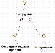
Figure 13. The generalization relationship between actors
Actors, use cases, and relationships are key elements of the use-case diagram notation. The use-case diagram helps to display the basic requirements for the simulated system and to ensure a mutual understanding of the functionality of the system between the developer and the customer. It is possible to construct one, main chart of precedents, which will reflect the boundaries of the system (actors) and its main functionality (precedents). For a more detailed representation of the system, auxiliary use case diagrams are allowed.

Comments
To leave a comment
Computer Engineering Technologies
Terms: Computer Engineering Technologies