Lecture
In StarUML, the main use case diagram is called Main and is located in the Use Case view. If in the model navigator click
two times by the name of this diagram, then its working field will open. To create a use case, click on the oval use case icon in the toolbar to the left of the chart's working area, and then click the place in the chart's working area where you want to place the use case. Similarly, an actor is created. When an element is placed on the chart field, it becomes available for editing the name and some properties. In the highlighted field, enter the new name of the use case or actor (Fig. 14).
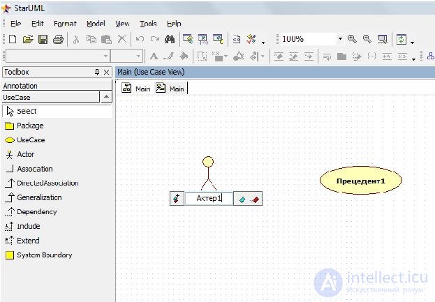
Figure 14. Naming elements in StarUML
To create a relationship between the chart elements, click on the image of the corresponding relationship in the toolbox on the right, and then draw a line from one element to another, holding down the left mouse button (Fig. 15).
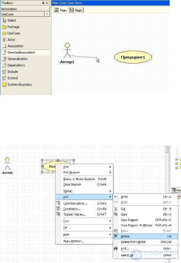
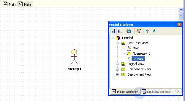
Figure 17. The Use Case1 element is removed from the chart field, but displayed in the model navigator.
If we change our mind and decide to return the element to the chart, this can be done by dragging it from the model navigator to the chart field.
To delete an element from the model, click on it in the diagram or on its image in the model navigator with the right mouse button and select the Delete from Model item in the context menu. The item will be completely removed.
The methods of adding and deleting elements and relations described above can be used to build diagrams of any type. We will not further focus on this reader. Note that all the described operations are also available from the main menu.
StarUML.
Example. For the order system of the Style shop, we identified the actors Buyer, Employee, Warehouse System and precedents Ordering goods, Managing order status, Obtaining order information. Construct the main use case diagram (Fig. 18).

Figure 18. The main diagram of options for using the order shop system "Style"
For the actor, the Buyer and the precedent Order of goods established the relationship of the directed association: The order of goods is initialized by the Buyer. The employee has the ability to manage the status of the order, while he certainly participates in the precedent Obtaining information about the order. Directed association from Retrieving order information to
to the actor System Warehouse can be understood as the automatic transfer of data from the simulated system to the warehouse supply system.
The model should include a brief description of each actor or precedent, this is done to ensure that between the developer and the customer of the system there are no “white spots” and discrepancies in understanding the functionality of the system and the roles of actors interacting with it. For each actor, the role he plays in the system is described, and for each precedent his role and functionality are described. You can also specify how the actor starts the precedent.

Comments
To leave a comment
Computer Engineering Technologies
Terms: Computer Engineering Technologies