Lecture
Consider the basic elements of the notation of activity diagrams. They illustrate activities, transitions between them, elements of choice and synchronization.
Activity is the execution of a particular behavior in a system control flow. In UML, activity is depicted as a rounded rectangle with a text description inside.
Example. Activity denotes a step (stage) of the process. In the precedent Ordering goods one of these steps can be Add a product to the basket (Fig. 23).
Figure 23. Activities
A transition indicates how the flow of control passes from one activity to another. Usually the transition is carried out at the end of the activity (Fig. 24).
Example. In our example, by performing the Order of goods, the buyer canOpen the cart and Remove the goods from it. These are two different activities, the transition to the removal of goods is possible only after opening the basket.

Figure 24. Transition between activities
Two states on the activity diagram - the initial and final - determine the duration of the flow. The initial state must be marked on the diagram; it defines the beginning of the flow. There may be several or more end states. It defines the end point of the stream. There may be several end states, but the initial state should be only one. The initial state is represented by a bold point, and the final state is represented by a bold point in a circle (Fig. 25).
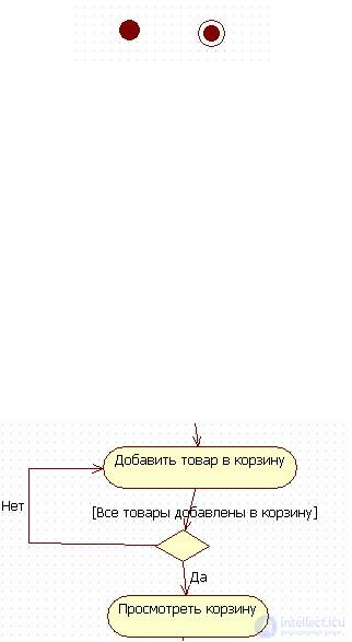
Figure 26. Transition condition between activities
Figure 25. Designations of the initial and final states
When modeling the control flows of a system, it is often necessary to show the places of their separation on the basis of a conditional choice. The selection on the diagram is shown by a diamond placed on the transition. The restrictive conditions on which the choice of the direction of transition depends are usually placed above the diamond. In UML notation, conditions are written in square brackets: [condition].
Example. If all the goods that the buyer wants to order, are added to the basket, the buyer can view the basket and place an order. The transition condition from the activity Add product to cart To View cart on the chart can be shown as
Synchronization - This is a way to show that two or more thread branches are executed in parallel.
Activities placed between two bold lines in the activity diagram are executed simultaneously and simultaneously.
Example. After the buyer has paid for the order, the system assigns a unique number to the order and sends an order confirmation to the electronic
Buyer mail. These two activities can be performed synchronously. As shown in the diagram, shown in Figure 27.
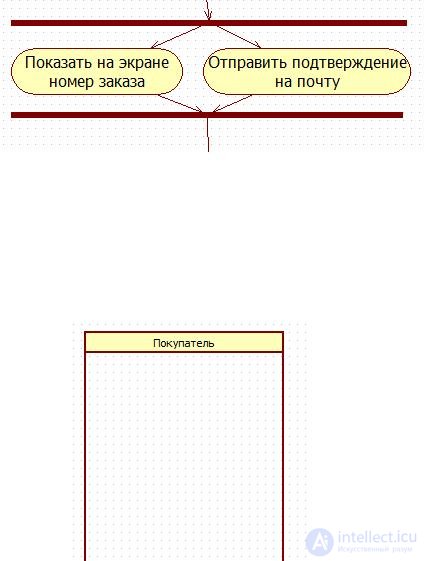
Figure 28. Section
The sections divide the activity diagram into several sections. This is necessary in order to show who is responsible for carrying out the activity and in what order. If the activity is on the section with the name Buyer, then this actor performs it.
Example. Section of the actor Buyer is depicted in Figure 28.

Comments
To leave a comment
Computer Engineering Technologies
Terms: Computer Engineering Technologies