Lecture
The basis of the trans port GOVERNMENTAL means of TCP / IP protocol stack of protocol interworking - Internet Protocol (IP). The main functions of the IP protocol include:
An IP packet consists of a header and a data field. The package header has the following fields:
The maximum length of the data field of a packet is limited by the length of the field that defines this value and is 65535 bytes, however, when transmitting over different types of networks, the packet length is selected taking into account the maximum length of the lower layer protocol packet carrying IP packets. If these are Ethernet frames, then packets with a maximum length of 1500 bytes that fit in the data field of the Ethernet frame are selected.
The transport layer protocols (TCP or UDP) that use the network layer to send packets assume that the maximum data field size of an IP packet is 65535, and therefore can send a message of that length to it for transport over the internetwork. The functions of the IP layer include splitting a message that is too long for a specific type of network component into shorter packets with the creation of appropriate service fields necessary for the subsequent assembly of fragments into the original message.
Most types of local and wide area networks define such a concept as the maximum size of the data field of a frame or packet, in which the IP protocol must encapsulate its packet. This value is commonly referred to as the Maximum Transfer Unit, MTU . Ethernet networks have an MTU of 1500 bytes, FDDI networks have 4096 bytes, and X.25 networks most often operate with an MTU of 128 bytes.
Figure 4.1 illustrates how Internet Protocol (IP) fragmentation of packets in hosts and routers works.
Let Computer 1 be connected to a network with an MTU of 4096 bytes, such as an FDDI network. When a message from the transport layer of 5600 bytes arrives at the IP layer of computer 1, the IP protocol divides it into two IP packets, setting the fragmentation flag in the first packet and assigning a unique identifier to the packet, for example, 486. In the first packet, the value of the offset field is 0, and in the second - 2800. The fragmentation sign in the second packet is equal to zero, which indicates that this is the last fragment of the packet. The total IP packet size is 2800 + 20 (IP header size), that is, 2820 bytes, which fits into the data field of the FDDI frame.
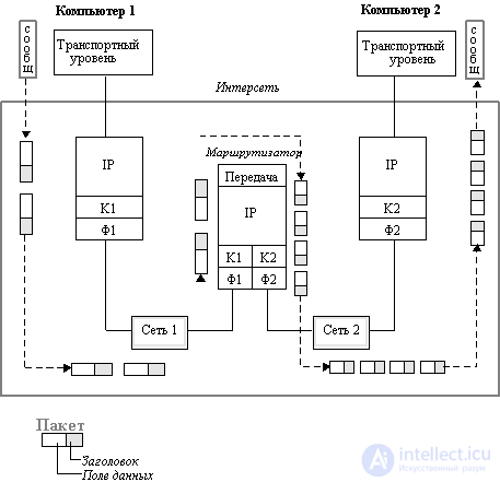
Figure: 4.1. Fragmentation of IP packets between networks with different
maximum packet sizes. K1 and F1 channel and physical layer of network 1,
K2 and F2 channel and physical layer of network 2
Further, computer 1 transmits these packets to the K1 data link layer, and then to the F1 physical layer, which sends them to the router associated with this network.
The router sees from the network address that the arrived two packets must be sent to network 2, which has a lower MTU value of 1500. This is probably an Ethernet network. The router extracts the transport message fragment from each FDDI packet and halves it further to fit each part into the data field of the Ethernet frame. It then generates new IP packets, each one 1400 + 20 = 1420 bytes long, which is less than 1500 bytes, so they fit normally in the data field of Ethernet frames.
As a result, four IP packets with a common ID of 486 arrive over Ethernet to computer 2, which allows the IP protocol running in computer 2 to correctly assemble the original message. If packets arrived in a different order than they were sent, then the offset will indicate the correct order of combining.
Note that IP routers do not reassemble packet fragments into larger packets, even if there is a network in the way that allows for such aggregation. This is due to the fact that individual message fragments can travel on the Internet along different routes, so there is no guarantee that all fragments pass through any intermediate router in their path.
When the first fragment of a packet arrives, the destination node starts a timer that determines the maximum allowable waiting time for the remaining fragments of this packet to arrive. If the timer expires before the arrival of the last fragment, then all the fragments of the packet received so far are discarded, and an error message is sent to the node that sent the original packet using the ICMP protocol.
Let us now consider the principles on the basis of which in IP networks the choice of the packet transmission route between networks occurs.
First, you need to pay attention to the fact that not only routers, but also end nodes - computers - must participate in the selection of the route. The example in Figure 4.2 demonstrates this need. There are several routers on the LAN here, and the computer must choose which one to send the packet to.

Figure: 4.2. End-node Router Selection
The length of the route can change significantly depending on which router the computer chooses to transmit its packet to a server located, for example, in Germany, if Router 1 is connected by a dedicated line to a router in Copenhagen, and Router 2 has a satellite link connecting it to Tokyo ...
In the TCP / IP stack, routers and end nodes make decisions about who to send a packet to in order to successfully deliver it to its destination based on so-called routing tables.
The following table is a typical example of a route table using network IP addresses:
Destination network address |
Next Router Address | Output port number |
Distance to destination network |
||||||||||||||||||||||||||||||||||||||||||||||||||||||||||||||||||||||||||||||||||||||||||||||||||||||||||||||||||||||||||||||||||||||||||||||||||||||||||
| 56.0.0.0 | 198.21.17.7 | 1 | 20 | ||||||||||||||||||||||||||||||||||||||||||||||||||||||||||||||||||||||||||||||||||||||||||||||||||||||||||||||||||||||||||||||||||||||||||||||||||||||||||
| 56.0.0.0 | 213.34.12.4. | 2 | 130 | ||||||||||||||||||||||||||||||||||||||||||||||||||||||||||||||||||||||||||||||||||||||||||||||||||||||||||||||||||||||||||||||||||||||||||||||||||||||||||
| 116.0.0.0 | 213.34.12.4 | 2 | 1450 | ||||||||||||||||||||||||||||||||||||||||||||||||||||||||||||||||||||||||||||||||||||||||||||||||||||||||||||||||||||||||||||||||||||||||||||||||||||||||||
| 129.13.0.0 | 198.21.17.6 | 1 | 50 | ||||||||||||||||||||||||||||||||||||||||||||||||||||||||||||||||||||||||||||||||||||||||||||||||||||||||||||||||||||||||||||||||||||||||||||||||||||||||||
| 198.21.17.0 | - | 2 | 0 | ||||||||||||||||||||||||||||||||||||||||||||||||||||||||||||||||||||||||||||||||||||||||||||||||||||||||||||||||||||||||||||||||||||||||||||||||||||||||||
| 213.34.12.0 | - | 1 | 0 | ||||||||||||||||||||||||||||||||||||||||||||||||||||||||||||||||||||||||||||||||||||||||||||||||||||||||||||||||||||||||||||||||||||||||||||||||||||||||||
| default | 198.21.17.7 | 1 | - | ||||||||||||||||||||||||||||||||||||||||||||||||||||||||||||||||||||||||||||||||||||||||||||||||||||||||||||||||||||||||||||||||||||||||||||||||||||||||||
In this table, the column "Destination network address" contains the addresses of all networks to which this router can forward packets. The TCP / IP stack adopts the so-called one - step approach to optimize the packet forwarding route (next-hop routing) - each router and end node takes part in the selection of only one step of packet transmission. The site https://intellect.icu says about it. Therefore, each line of the routing table does not indicate the entire route in the form of a sequence of IP addresses of routers through which the packet must pass, but only one IP address - the address of the next router to which the packet must be transmitted. Along with the packet, the responsibility for choosing the next hop is passed to the next router. A one-step approach to routing means a distributed solution to the route selection problem. This removes the limitation on the maximum number of transit routers in a packet's path.
(An alternative to the one-hop approach is to specify in the packet the entire sequence of routers that the packet must pass along its path. This approach is called Source Routing. In this case, the choice of the route is made by the end node or the first router along the path of the packet, and all other routers only process the selected route by switching packets, that is, transmitting them from one port to another.The Source Routing algorithm is used in IP networks only for debugging, when the route is specified in the IP OPTIONS field of the packet.)
If there is more than one line in the route table corresponding to the same destination network address, then when deciding whether to transmit a packet, the line in which the smallest value is indicated in the "Distance to destination network" field is used.
In this case, distance is understood as any metric used in accordance with the class of service specified in the network package. This can be the number of transit routers in a given route (the number of hops from a hop - a hop), the time it takes for a packet to travel through communication lines, the reliability of communication lines, or another value that reflects the quality of a given route in relation to a specific class of service. If the router supports several classes of service packets, then the route table is compiled and applied separately for each type of service (route selection criterion).
To send a packet to the next router, knowledge of its local address is required, but in the TCP / IP stack it is customary to use only IP addresses in routing tables to maintain their universal format, regardless of the type of networks included in the internetwork. To find a local address from a known IP address, you must use the ARP protocol.
The end node, like a router, has at its disposal a routing table of a unified format and, on the basis of its data, makes a decision to which router needs to send a packet for network N. The decision that this packet needs to be routed at all is made by the computer when he sees that the address of the packet's destination network differs from the address of his own network (during configuration, the administrator assigns each computer its IP address or several IP addresses if the computer is simultaneously connected to several networks). When the computer has selected the next router, it looks at the cache table of its ARP addresses and, perhaps, finds there a match between the IP address of the next router and its MAC address. If not,then an ARP broadcast request is sent over the local network and the local address is extracted from the ARP response.
After that, the computer generates a frame of the protocol used on the selected port, for example, an Ethernet frame, into which it puts the MAC address of the router. The router receives the Ethernet frame, extracts the IP packet from it, and looks through its routing table to find the next router. In doing so, it performs the same actions as the end node.
One-hop routing has another advantage - it allows you to reduce the size of the routing tables in end nodes and routers by using the so-called default route as the destination network number, which usually occupies the last row in the routing table. If there is such an entry in the routing table, then all packets with network numbers that are not in the routing table are forwarded to the router specified in the default line ... Therefore, routers often store limited information about the networks on the internetwork in their tables, forwarding packets for the rest of the networks to the default port and router. It is assumed that the default router will forward the packet to the backbone, and the routers connected to the backbone are fully aware of the composition of the internetwork.
End-nodes are especially common in the default routing technique. While they also generally have a routing table at their disposal, the size is usually negligible since routing is not the main business for the computer. The main role in routing packets in the concept of IP is naturally assigned to routers, which must have much more complete routing tables than end nodes. An end node often operates without a routing table at all, only knowing the IP address of the default router. If there is one router in the local network, this option is the only one possible for all end nodes. But even if there are several routers in the local network, when the problem of choosing them is facing the end node,default routing is often used by computers to reduce the size of their routing table.
Another way to relieve the computer from the need to maintain large routing tables is to obtain information from the router about the rational route for a particular network using the ICMP protocol.
In addition to the default route, there are two types of special entries in the routing table — an entry for a host-specific route and an entry for the addresses of networks directly connected to the router's ports.
A node-specific route contains a full IP address instead of a network number, that is, an address that has non-zero information not only in the network number field, but also in the node number field. It is assumed that for such an end node, the route should be chosen differently than for all other nodes of the network to which it belongs. In the case when the table contains different records on the forwarding of packets for the entire network N and its separate node with the address N, D, when a packet addressed to the node N, D arrives, the router will give preference to the record for N, D.
Routing table entries for networks directly connected to the router contain zeros in the Distance to Destination Network field.
Another difference between a router and an end-node when choosing a route is the way the routing table is built. While routers usually automatically create routing tables by exchanging service information, for end nodes, routing tables are usually created manually by administrators and stored as permanent files on disks.
There are various algorithms for building tables for one-hop routing. They can be divided into three classes:
Regardless of the algorithm used to build the routing table, the result of their work has a uniform format. Due to this, in the same network, various nodes can build routing tables according to their algorithms, and then exchange missing data among themselves, since the formats of these tables are fixed. Therefore, an adaptive router can provide an end node using a fixed routing algorithm with path information to a network that the end node knows nothing about.
Fixed routing
This algorithm is used in networks with a simple link topology and is based on manual creation of the routing table by the network administrator. The algorithm often works well for the backbones of large networks as well, since the backbone itself can have a simple structure with obvious best packet paths in the subnets attached to the backbone.
A distinction is made between single-route tables, in which one path is specified for each destination, and multi-route tables, which define several alternative paths for each destination. When using multi-route tables, a rule for selecting one of them must be specified. Most often, one path is the main path, and the rest are backup.
Simple routing
Simple routing algorithms fall into three subclasses:
Adaptive routing
This is the main type of routing algorithms used by routers in today's complex topology networks. Adaptive routing is based on the fact that routers periodically exchange specific topological information about the networks available on the internetwork, as well as about the connections between the routers. Usually, not only the topology of links is taken into account, but also their bandwidth and state.
Adaptive protocols allow all routers to collect information about the topology of links in the network, quickly processing all changes in the link configuration. These protocols are distributed in nature, which is expressed in the fact that there are no dedicated routers in the network that would collect and summarize topological information: this work is distributed among all routers.
Let us consider, using the example of the internetwork shown in Figure 4.3, how computers interact through routers and deliver packets to the destination computer.
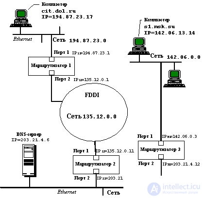
Figure: 4.3. An example of the interaction of computers through the internetwork
Let in the given example the user of the computer cit.dol.ru, located in the Ethernet network with the IP address 194.87.23.0 (class C address), wants to communicate via FTP with the computer s1.msk.su, belonging to the Ethernet network with the IP address 142.06 .0.0 (class B address). Computer cit.dol.ru has IP address 194.87.23.1.17, and computer s1.msk.su has IP address 142.06.13.14.
1. The computer user cit.dol.ru knows the symbolic name of the computer s1.msk.su, but does not know its IP address, so he types the command
> ftp s1.msk.su
to organize an ftp session.
The computer cit.dol.ru must have some parameters set for the TCP / IP stack in order for it to perform the task assigned to it.
These parameters should include your own IP address, the DNS server IP address, and the default router IP address. Since only one router is connected to the Ethernet network to which the cit.dol.ru computer belongs, the routing table is not needed for the end nodes of this network; it is enough to know the default router IP address. In this example, it is equal to 194.87.23.1.
Since the user in the ftp command did not specify the IP address of the host he wants to interact with, the TCP / IP stack must determine it on its own. It can query the DNS server at the IP address it has, but usually each computer looks first at its own table of symbolic names and IP addresses. Such a table is most often stored as a text file of a simple structure - each line of it contains an entry about one symbolic name and its IP address. In Unix OS, such a file is traditionally named HOSTS.
2. Let's assume that the computer cit.dol.ru has the HOSTS file, and it contains the line
142.06.13.14 s1.msk.su.
Therefore, name resolution is performed locally, so that the IP protocol can now generate IP packets with a destination address of 142.06.13.14 to communicate with the s1.msk.su computer.
3. The IP protocol of the cit.dol.ru computer checks whether it is necessary to route packets for the address 142.06.13.14. Since the destination network address is 142.06.0.0, and the network address to which the computer belongs is 194.87.23.0, routing is necessary.
4. Computer cit.dol.ru starts generating an Ethernet frame to send an IP packet to the default router with the IP address 194.87.23.1. To do this, he needs the MAC address of the port of the router connected to his network. This address is most likely already in the computer's ARP cache table if it has exchanged data with computers on other networks at least once during the last activation. Let this address in our example was found in the cache memory. Let's designate it as MAC 11 , in accordance with the number of the router and its port.
5. As a result, the cit.dol.ru computer sends an Ethernet frame over the local network with the following fields:
| DA (Ethernet) | ... | DESTINATION IP | ... | ... | |||||||||||||||||||||||||||||||||||||||||||||||||||||||||||||||||||||||||||||||||||||||||||||||||||||||||||||||||||||||||||||||||||
| MAC 11 | 142.06.13.14 | ||||||||||||||||||||||||||||||||||||||||||||||||||||||||||||||||||||||||||||||||||||||||||||||||||||||||||||||||||||||||||||||||||||||
6. The frame is received by port 1 of router 1 in accordance with the Ethernet protocol, since the MAC node of this port recognizes its MAC address 11 . The Ethernet protocol extracts an IP packet from this frame and passes it on to the IP router software. IP extracts the destination address from the packet and looks at the entries in its routing table. Let Router 1 have an entry in its routing table
142.06.0.0 135.12.0.11 2 1,
which says that the packets for the network are 142.06. 0.0 must be passed to Router 135.12.0.11, which is connected to the same network as Port 2 on Router 1.
7. Router 1 looks at the parameters of port 2 and finds that it is connected to the FDDI network. Since the FDDI network has a maximum transportable MTU value greater than the Ethernet network, fragmentation of the data field of the IP packet is not required. Therefore, router 1 generates an FDDI frame, in which it indicates the MAC address of the port of router 2, which it finds in its ARP protocol cache table:
| DA (FDDI) | ... | DESTINATION IP | ... | ... | ||||||||||||||||||||||||||||||||||||||||||||||||||||||||||||||||||||||||||||||||||||||||||||||||||||||||||||||||||||||||||||||||||||||||||
| MAC 21 | 142.06.13.14 | |||||||||||||||||||||||||||||||||||||||||||||||||||||||||||||||||||||||||||||||||||||||||||||||||||||||||||||||||||||||||||||||||||||||||||||
8. Router 2 acts in a similar way, forming an Ethernet frame for transmitting a packet to router 3 over an Ethernet network with an IP address of 203.21.4.0:
| DA (Ethernet) | ... | DESTINATION IP | ... | ... | |||||||||||||||||||||||||||||||||||||||||||||||||||||||||||||||||||||||||||||||||||||||||||||||||||||||||||||||||||||||||||||||||||||||||||
| MAC 32 | 142.06.13.14 | ||||||||||||||||||||||||||||||||||||||||||||||||||||||||||||||||||||||||||||||||||||||||||||||||||||||||||||||||||||||||||||||||||||||||||||||
9. Finally, after the packet arrives at the destination network router - Router 3, it becomes possible to transmit this packet to the destination computer. Router 3 sees that the packet needs to be forwarded to the 142.06.0.0 network, which is directly connected to its first port. Therefore, it sends an ARP request over the Ethernet network with the IP address of the computer s1.msk.su (we believe that this information is not in its cache), receives a response containing the MAC address s1 , and generates an Ethernet frame that delivers the IP packet over the local network to the destination.
| DA (Ethernet) | ... | DESTINATION IP | ... | ... | ||||||||||||||||||||||||||||||||||||||||||||||||||||||||||||||||||||||||||||||||||||||||||||||||||||||||||||||||||||||||||||||||||||||||||
| MAC s1 | 142.06.13.14 | |||||||||||||||||||||||||||||||||||||||||||||||||||||||||||||||||||||||||||||||||||||||||||||||||||||||||||||||||||||||||||||||||||||||||||||
Often, network administrators experience inconvenience because the number of centrally allocated network numbers is not enough to structure the network properly, for example, to place all weakly interacting computers on different networks.
In this situation, two ways are possible. The first is related to obtaining additional network numbers from the NIC. The second method, which is used more often, is associated with the use of so-called masks , which allow you to divide one network into several networks.
A mask is a number whose binary notation contains ones in those digits that should be interpreted as a network number.
For example, for standard network classes, masks have the following meanings:
255.0.0.0 - mask for class A network,
255.255.0.0 - mask for class B network,
255.255.255.0 - mask for a class C network.
In the masks that the administrator uses to increase the number of networks, the number of ones in the sequence defining the boundary of the network number does not have to be a multiple of 8 in order to repeat the division of the address into bytes.
For example, suppose the mask is 255.255.192.0 (11111111 11111111 11000000 00000000). And let the network have the number 129.44.0.0 (10000001 00101100 00000000 00000000), from which it can be seen that it belongs to class B. After the mask was applied to this address, the number of digits interpreted as the network number increased from 16 to 18, that is, the administrator received the ability to use instead of one centrally assigned network number, four:
129.44.0.0 (10000001 00101100 00000000 00000000)
129.44.64.0 (10000001 00101100 01000000 00000000)
129.44.128.0 (10000001 00101100 10000000 00000000)
129.44.192.0 (10000001 00101100 11000000 00000000)
For example, the IP address 129.44.141.15 (10000001 00101100 10001101 00001111), which by IP standards specifies the network number 129.44.0.0 and the node number 0.0.141.15, will now be interpreted as a pair when using a mask:
129.44.128.0 - network number, 0.0. 13.15 - node number.
Thus, by setting a new value for the mask, you can make the router interpret the IP address differently. However, the last two additional bits of the network number are often interpreted as subnet numbers.
One more example. Let some network belongs to class B and has the address 128.10.0.0 (Figure 4.4). This address is used by the router that connects the network to the rest of the internetwork. And let among all the stations of the network there are stations that weakly interact with each other. It would be desirable to isolate them in different networks. To do this, the network can be divided into two networks, connecting them to the corresponding ports of the router, and setting for these ports as a mask, for example, the number 255.255.255.0, that is, organizing two class C subnets within the source network with a centrally specified number (one could select a different size for the subnet address field). From the outside, the network will still look like a single class B network, but at the local level it will be two separate class C networks. The incoming general traffic will be divided by the local router between the subnets.
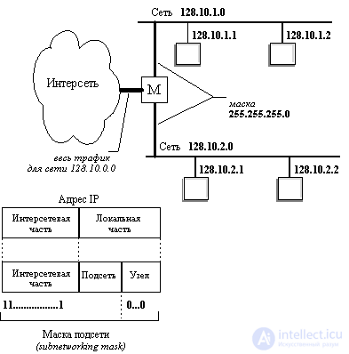
Figure: 4.4. An example of using masks to structure a network
It should be noted that if a decision is made to use the mask mechanism, then both the routers and the computers on the network must be configured accordingly.
Port is a digital number that is a software address used for the interaction of various endpoints (network devices, hosts) in modern computer networks at the transport layer of the OSI model. Ports are used in transport protocols TCP, UDP, SCTP, DCCP and allow different programs and network services on the same host to receive data in IP packets independently of each other. Any interaction between two hosts implies the use of at least one destination port, and usually the source port. The port number added to the computer's IP address completes the identification of a possible communication session. That is, data packets are sent over the network to a specific destination IP address, and then, upon reaching the destination computer, they are further directed to a specific process associated with the destination port number.How ports are used depends on the protocol that uses them. The destination host port of a particular networking is usually known to the application in advance. The host port of the source of the network packet can be assigned both dynamically for each new communication session, or it can be constant, static. For TCP-connection, the port of the sending host is especially important, since it is on it that the answer and confirmation should come delivery of the package from the receiving host. For SCTP, an association can use multiple source host ports and multiple destination host ports (thus, this protocol achieves higher session reliability and transmission speed). If a certain number is permanently assigned to a certain program on the host and can be constantly used to receive and / or transmit data, then they say that such a port is "open". Similar terminology is an open port or a closed (blocked) port used in network firewalls. If a particular program is waiting for a transmission on a particular port and keeps it open, the program is said to be "listening on a port". Port numbers recommended and used for specific specific purposes, i.e. for network services,allocates and registers the IANA (Internet Assigned Numbers Authority), but in practice there are often cases of their informal use.
Wikibooks logo There is a wikibook on the topic
"Port ( computer networks )"
Due to the significant spread of the TCP and UDP protocols, most often mentioning ports on the network means ports for these transport protocols. Network services in SCTP and DCCP usually use numbers that match their TCP and UDP implementations (if available).
The port number is a 16-bit binary integer, so ports are possible in the range 1 to 65535 (for TCP, port number 0 is reserved and cannot be used). For UDP, the source port is optional and zero means no port.
Source and destination ports
TCP or UDP packets always contain two port number fields: source and destination. The type of service program is determined by the port of the receiver of the incoming requests, and this number is the port of the sender of the replies. The "reverse" port (the port of the sender of requests, it is also the port of the recipient of responses) when connecting via TCP is determined by the client arbitrarily (although numbers less than 1024 and already occupied ports are not assigned), and is not of interest to the user.
The use of reverse port numbers in UDP is implementation dependent.
Port States
Active ports of transport layer protocols on many operating systems (Windows, Unix-like) can be discovered using the NetStat command or nmap (on UNIX / Linux).
Possible port states are shown by netstat and nmap:
State Description
open the server program is ready to accept connections
listen the server is listening on this port
filtred firewall or some other reason prevents nmap from detecting whether the closed port is open or
closed
Comet technology is a model of a Web application, in which a persistent HTTP connection allows the Web server to send (push) data to the browser without an additional request from the browser [13, 14, 15, 16]. The name "Comet" is used to refer to a variety of techniques to achieve this interaction. What these methods have in common is that they are based on technologies directly supported by the browser, such as JavaScript, rather than plugins. In theory, Comet's approach differs from the original concept of the World Wide Web, in which the browser requests a page in whole or in part in order to refresh the page. In practice, however, Comet applications typically use "long polling" Ajax to check for new information on the server.
13.5.1. HTTP server push
HTTP server push (also called HTTP streaming) is a mechanism for sending data from a Web server to a Web browser (Fig. 13.4) [15]. HTTP server push can be implemented through several mechanisms. Primary is when the web server does not close the connection after sending a response to the client. The web server keeps the connection open, so if an event occurs, it can be sent to one or many clients. Otherwise, the data is queued until the next client request. Most servers implement this functionality through CGI (eg NPH scripts in Apache).
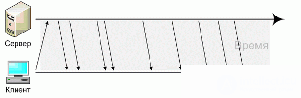
Figure: 13.4. How Comet works - HTTP-streaming
Another mechanism relates to a special MIME type called multipart / x-mixed-replace, which was introduced by Netscape in 1995. The web browser interprets this as document changes whenever the server reports a new version to the client. This is still supported today by Firefox, Opera and Safari, but traditionally ignored by Internet Explorer. This applies to HTML-documents, but also for streaming display images for applications working with webcams.
WHATWG Web Applications 1.0 suggests enabling a mechanism to "push" content to the client. On September 1, 2006, the Opera browser implemented this new experimental technology in a functionality called "Server-Sent Events". It is now part of the HTML5 standards. Another related part of HTML5 is Web Sockets, which are available in Google Chrome since version 4.0.249.0, and there are also JavaScript libraries that emulate Web Sockets.
Recently, one can often hear the expression real-time web , which is said to be the future of the Internet. In fact, it is a set of technologies that allows you to receive data added to the Web in real time. A special case of this idea is real-time search - real-time search .
At the moment, there are several real-time search engines, as well as several experiments from giants like Google. Some practical issues remain unresolved, for example, determining the relevance in search results, but the technology of transmitting data to the user's browser is quite efficient.
13.5.2. Pooling
One of the ways to find out if there are any updates on the server is to use AJAX technology and make a request to the server at a certain time interval (Fig. 13.5) [15].

Figure: 13.5. An example of asynchronous requests in AJAX - short polling
This type of interaction is called polling (from the English poll - to pull), and the browser is engaged in pulling data. The advantages over full page refresh are obvious, but there are also disadvantages. The main one is "idle work" - often the browser makes hundreds of requests, and in response it finds out that there is no new data. It was to solve this problem that the long polling technology appeared , which allows you to make queries that return the result as soon as it appears. An example of interaction is shown in Fig. 13.6 [15].
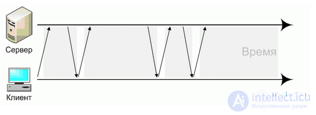
Figure: 13.6. An example of long asynchronous requests - long polling
This technique is the middle ground between simple AJAX and complex HTTP streaming . The main advantage is that the client creates only one connection through which it receives data from the server in real time. The main disadvantages are the complexity of the implementation and the inconsistency with the spirit of the HTTP protocol.

Comments
To leave a comment
Fundamentals of Internet and Web Technologies
Terms: Fundamentals of Internet and Web Technologies