Lecture
The vehicles of the TCP / IP protocol stack are based on the Internet Protocol (IP). The main functions of the IP protocol include:
An IP packet consists of a header and a data field. The package header has the following fields:
The maximum length of a packet's data field is limited by the field width defining this value, and is 65535 bytes, however, when transmitting over various types of networks, the packet length is selected taking into account the maximum length of a lower-level protocol packet carrying IP packets. If these are Ethernet frames, then packets with a maximum length of 1500 bytes are selected that fit in the data field of the Ethernet frame.
The transport layer protocols (TCP or UDP protocols), which use the network layer to send packets, consider that the maximum size of the data field of an IP packet is 65535, and therefore can send it a message of such length for transport via the inter net. The functions of the IP layer include splitting a message that is too long for a specific type of network component into shorter packets with the creation of corresponding service fields needed for the subsequent assembly of fragments into the original message.
In most types of local and global networks, such a concept is defined as the maximum size of a frame or packet data field into which the IP protocol should encapsulate. This value is usually called the maximum transfer unit - Maximum Transfer Unit, MTU . Ethernet networks have an MTU of 1500 bytes, FDDI networks have 4096 bytes, and X.25 networks most often work with a 128 byte MTU.
The operation of the IP protocol on packet fragmentation in hosts and routers is illustrated in Figure 4.1.
Let computer 1 be connected to a network that has an MTU value of 4096 bytes, for example, an FDDI network. When a message arrives at the IP level of computer 1 from the transport layer of 5600 bytes, the IP protocol divides it into two IP packets, setting a fragmentation flag in the first packet and assigning a unique identifier to the packet, for example, 486. In the first packet, the value of the offset field is 0, and in the second - 2800. The sign of fragmentation in the second packet is zero, which indicates that this is the last fragment of the packet. The total value of the IP packet is 2800 + 20 (the size of the IP header), that is 2820 bytes, which fits in the data field of the FDDI frame.
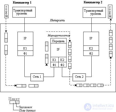
Fig. 4.1. Fragmentation of IP packets during transmission between networks with different
maximum packet sizes. K1 and F1 channel and physical layer network 1,
K2 and F2 channel and physical layer network 2
Next, computer 1 transmits these packets to the data link layer K1, and then to the physical layer F1, which sends them to the router connected to this network.
The router sees at the network address that the arriving two packets need to be transferred to network 2, which has a lower MTU value of 1500. This is probably an Ethernet network. The router extracts a fragment of the transport message from each FDDI packet and divides it further in half so that each part fits into the data field of the Ethernet frame. Then it forms new IP packets, each of which has a length of 1400 + 20 = 1420 bytes, which is less than 1500 bytes, so they normally fit in the Ethernet frame data field.
As a result, four IP packets with a common identifier 486 arrive at computer 2 via Ethernet, which allows the IP protocol running in computer 2 to correctly assemble the original message. If the packets did not arrive in the order in which they were sent, then the offset will indicate the correct order of their combination.
Note that IP routers do not assemble packet fragments into larger packets, even if there is a network on the way that allows such aggregation. This is due to the fact that individual fragments of a message can move across the internetwork along various routes, so there is no guarantee that all fragments pass through any intermediate router in their path.
When the first fragment of a packet arrives, the destination node starts a timer that determines the maximum allowable waiting time for the remaining fragments of this packet. If the timer expires before the last fragment arrives, then all fragments of the packet received by that moment are discarded, and an error message is sent to the node that sent the original packet using ICMP.
Let us now consider the principles on the basis of which the choice of a packet transmission route between networks takes place in IP networks.
First you need to pay attention to the fact that not only routers, but also end nodes - computers - should take part in choosing the route. The example shown in Figure 4.2 demonstrates this need. There are several routers in the local network, and the computer must choose which one to send a packet to.

Fig. 4.2. Selection of a router by an end node
The length of the route can vary significantly depending on which router chooses a computer to transfer its packet to a server located, for example, in Germany, if router 1 is connected by a dedicated line to a router in Copenhagen, and router 2 has a satellite channel connecting it to Tokyo .
In the TCP / IP stack, routers and end nodes make decisions about who should send the packet for successful delivery to the destination node, based on the so-called routing tables.
The following table is a typical example of a route table using network IP addresses:
| Network address destination | Next router address | Holiday number the port | Distance to destination networks | ||||||||||||||||||||||||||||||||||||||||||||||||||||||||||||||||||||||||||||||||||||||||||||||||||||||||||||||||||||||||||||||||||||||||||||||||||||||||||
| 56.0.0.0 | 198.21.17.7 | one | 20 | ||||||||||||||||||||||||||||||||||||||||||||||||||||||||||||||||||||||||||||||||||||||||||||||||||||||||||||||||||||||||||||||||||||||||||||||||||||||||||
| 56.0.0.0 | 213.34.12.4. | 2 | 130 | ||||||||||||||||||||||||||||||||||||||||||||||||||||||||||||||||||||||||||||||||||||||||||||||||||||||||||||||||||||||||||||||||||||||||||||||||||||||||||
| 116.0.0.0 | 213.34.12.4 | 2 | 1450 | ||||||||||||||||||||||||||||||||||||||||||||||||||||||||||||||||||||||||||||||||||||||||||||||||||||||||||||||||||||||||||||||||||||||||||||||||||||||||||
| 129.13.0.0 | 198.21.17.6 | one | 50 | ||||||||||||||||||||||||||||||||||||||||||||||||||||||||||||||||||||||||||||||||||||||||||||||||||||||||||||||||||||||||||||||||||||||||||||||||||||||||||
| 198.21.17.0 | - | 2 | 0 | ||||||||||||||||||||||||||||||||||||||||||||||||||||||||||||||||||||||||||||||||||||||||||||||||||||||||||||||||||||||||||||||||||||||||||||||||||||||||||
| 213. 34.12.0 | - | one | 0 | ||||||||||||||||||||||||||||||||||||||||||||||||||||||||||||||||||||||||||||||||||||||||||||||||||||||||||||||||||||||||||||||||||||||||||||||||||||||||||
| default | 198.21.17.7 | one | - | ||||||||||||||||||||||||||||||||||||||||||||||||||||||||||||||||||||||||||||||||||||||||||||||||||||||||||||||||||||||||||||||||||||||||||||||||||||||||||
In this table, the destination network address column indicates the addresses of all networks to which this router can transmit packets. The TCP / IP stack adopts the so-called one - step approach to optimizing the route of packet forwarding (next-hop routing) - each router and end node takes part in the selection of only one packet transfer step. Therefore, each row of the routing table does not indicate the entire route as a sequence of IP addresses of routers through which the packet must pass, but only one IP address — the address of the next router to which the packet should be sent. Together with the packet, the next router is responsible for choosing the next routing step. A one-step approach to routing means a distributed solution to the problem of choosing a route. This removes the limit on the maximum number of transit routers in the packet path.
(An alternative to the one-step approach is to specify in the packet the entire sequence of routers that the packet must pass in its path. This approach is called Source Routing. In this case, the route is chosen by the end node or the first router in the packet's path, and all other routers only work on the selected route, performing packet switching, that is, transferring them from one port to another.The Source Routing algorithm is used in IP networks only for debugging when the route is specified Field Allowance (IP OPTIONS) package.)
If there is more than one line in the route table that corresponds to the same destination network address, then when deciding whether to transfer a packet, the line with the lowest value in the "Distance to destination network" field is used.
In this case, the distance is any metric used in accordance with the class of service specified in the network package. This may be the number of transit routers in a given route (the number of hops from hop is a jump), the packet transit time on the communication lines, the reliability of communication lines, or another value reflecting the quality of this route in relation to a particular class of service. If the router supports several classes of packet service, the route table is compiled and applied separately for each type of service (route selection criteria).
To send a packet to the next router, knowledge of its local address is required, but in the TCP / IP stack, only IP addresses are used in the routing tables in order to preserve their universal format, independent of the type of networks that belong to the internetwork. To find a local address by a known IP address, you need to use the ARP protocol.
The end node, like the router, has at its disposal a routing table of a unified format and, based on its data, decides to which router the packet should be sent for the network N. The computer decides that this packet should be routed at all. he sees that the destination network address of the packet is different from the address of his own network (when configuring, the administrator assigns his IP address or several IP addresses to each computer if the computer is simultaneously connected to kim networks). When the computer has selected the next router, it scans the cache table of addresses of its ARP protocol and, perhaps, finds there the correspondence of the IP address of the next router to its MAC address. If not, a broadcast ARP request is transmitted over the local network and the local address is extracted from the ARP response.
After that, the computer forms the frame of the protocol used on the selected port, for example, the Ethernet frame, into which it places the MAC address of the router. The router takes an Ethernet frame, extracts an IP packet from it, and scans its routing table to find the next router. In doing so, it performs the same actions as the end node.
One-step routing has another advantage: it reduces the amount of routing tables in the end nodes and routers by using the default route, the default route, which usually occupies the last row in the routing table. If there is such an entry in the routing table, then all packets with network numbers that are not in the routing table are forwarded to the router specified in the default row. Therefore, routers often store limited information about internetworks in their tables, sending packets for other networks to the port and router used by default. It is assumed that the default router will transmit the packet to the backbone network, and routers connected to the trunk have full information about the composition of the internetwork.
Especially often the end nodes use default routing. Although they also generally have a routing table at their disposal, its size is usually insignificant, since routing for a computer is not the main occupation. The main role in packet routing in the IP protocol concept is naturally assigned to routers, which should have much more complete routing tables than end nodes. The end node often works without a routing table at all, having only information about the default IP address of the router. With a single router on the local network, this option is the only one possible for all end nodes. But even if there are several routers in the local network, when the problem of their choice is facing the end node, the default route setting is often used in computers to reduce the size of their routing table.
Another way to offload a computer from having to maintain large routing tables is to get information from a router about a rational route for any particular network using ICMP.
In addition to the default route, there are two types of special entries in the routing table — an entry for a host-specific route and an entry for the addresses of networks directly connected to the ports of the router.
A node-specific route instead of a network number contains a full IP address, that is, an address that has non-zero information not only in the network number field, but also in the node number field. It is assumed that for such an end node the route should be chosen differently than for all other nodes of the network to which it belongs. In the case when the table has different packet forwarding records for the entire network N and its separate node having the address N, D, when a packet is addressed to node N, D, the router will prefer the record for N, D.
Routing table entries related to networks directly connected to the router contain zeroes in the "Distance to destination network" field.
Another difference between the work of the router and the end node when choosing a route is the way to build a routing table. If routers usually automatically create routing tables, exchanging service information, then routing tables for end nodes are created, as a rule, manually by administrators, and are stored as permanent files on disks.
There are various algorithms for constructing tables for one-step routing. They can be divided into three classes:
Regardless of the algorithm used to build the routing table, the result of their work has a single format. Due to this, different nodes in the same network can build routing tables according to their algorithms, and then exchange the missing data among themselves, since the formats of these tables are fixed. Therefore, an adaptive routing router can provide the end node using the fixed routing algorithm with information about the path to the network about which the end node knows nothing.
Fixed routing
This algorithm is used in networks with a simple connection topology and is based on the manual creation of the routing table by the network administrator. The algorithm often works efficiently also for the backbones of large networks, since the backbone itself can have a simple structure with obvious best paths for packets on the subnet connected to the backbone.
Distinguish between single-route tables, in which one destination is given for each destination, and multi-route tables, which define several alternative ways for each destination. When using multipath tables, the rule for selecting one of them should be specified. Most often, one path is the main path, and the rest are backup.
Simple routing
Simple routing algorithms are divided into three subclasses:
Adaptive Routing
This is the main type of routing algorithms used by routers in modern networks with a complex topology. Adaptive routing is based on the fact that routers periodically exchange special topological information about the networks available in the internetwork, as well as about the connections between routers. Usually not only the topology of connections is taken into account, but also their throughput and state.
Adaptive protocols allow all routers to collect information about the topology of connections in the network, promptly practicing all changes in the configuration of connections. These protocols have a distributed nature, which is expressed in the fact that there are no dedicated routers in the network that would collect and summarize topological information: this work is distributed among all routers.
Рассмотрим на примере интерсети, приведенной на рисунке 4.3, каким образом происходит взаимодействие компьютеров через маршрутизаторы и доставка пакетов компьютеру назначения.
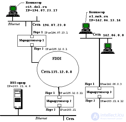
Fig. 4.3. Пример взаимодействия компьютеров через интерсеть
Пусть в приведенном примере пользователь компьютера cit.dol.ru, находящийся в сети Ethernet с IP-адресом 194.87.23.0 (адрес класса С), хочет взаимодействовать по протоколу FTP с компьютером s1.msk.su, принадлежащем сети Ethernet с IP-адресом 142.06.0.0 (адрес класса В). Компьютер cit.dol.ru имеет IP-адрес 194.87.23.1.17, а компьютер s1.msk.su - IP-адрес 142.06.13.14.
1. Пользователь компьютера cit.dol.ru знает символьное имя компьютера s1.msk.su, но не знает его IP-адреса, поэтому он набирает команду
> ftp s1.msk.su
для организации ftp-сеанса.
Some parameters for the TCP / IP stack must be set in the computer cit.dol.ru so that it can perform the task set for it.
These parameters should include your own IP address, DNS server IP address and default router IP address. Since only one router is connected to the Ethernet network to which the computer cit.dol.ru belongs, the routing table for the end nodes of this network is not needed, it is enough to know the default IP address of the router. In this example, it is 194.87.23.1.
Так как пользователь в команде ftp не задал IP-адрес узла, с которым он хочет взаимодействовать, то стек TCP/IP должен определить его самостоятельно. Он может сделать запрос к серверу DNS по имеющемуся у него IP-адресу, но обычно каждый компьютер сначала просматривает свою собственную таблицу соответствия символьных имен и IP-адресов. Такая таблица хранится чаще всего в виде текстового файла простой структуры - каждая его строка содержит запись об одном символьном имени и его IP-адресе. В ОС Unix такой файл традиционно носит имя HOSTS.
2. Будем считать, что компьютер cit.dol.ru имеет файл HOSTS, а в нем есть строка
142.06.13.14 s1.msk.su.
Поэтому разрешение имени выполняется локально, так что протокол IP может теперь формировать IP-пакеты с адресом назначения 142.06.13.14 для взаимодействия с компьютером s1.msk.su.
3. Протокол IP компьютера cit.dol.ru проверяет, нужно ли маршрутизировать пакеты для адреса 142.06.13.14. Так как адрес сети назначения равен 142.06.0.0, а адрес сети, к которой принадлежит компьютер, равен 194.87.23.0, то маршрутизация необходима.
4. Компьютер cit.dol.ru начинает формировать кадр Ethernet для отправки IP-пакета маршрутизатору по умолчанию с IP-адресом 194.87.23.1. Для этого ему нужен МАС-адрес порта маршрутизатора, подключенного к его сети. Этот адрес скорее всего уже находится в кэш-таблице протокола ARP компьютера, если он хотя бы раз за последнее включение обменивался данными с компьютерами других сетей. Пусть этот адрес в нашем примере был найден именно в кэш-памяти. Обозначим его МАС 11 , в соответствии с номером маршрутизатора и его порта.
5. As a result, the computer cit.dol.ru sends an Ethernet frame over the local network that has the following fields:
| DA (Ethernet) | ... | DESTINATION IP | ... | ... | |||||||||||||||||||||||||||||||||||||||||||||||||||||||||||||||||||||||||||||||||||||||||||||||||||||||||||||||||||||||||||||||||||
| MAS 11 | 142.06.13.14 | ||||||||||||||||||||||||||||||||||||||||||||||||||||||||||||||||||||||||||||||||||||||||||||||||||||||||||||||||||||||||||||||||||||||
6. The frame is received by port 1 of router 1 in accordance with the Ethernet protocol, since the MAC node of this port recognizes its MAC address 11 . The Ethernet protocol extracts an IP packet from this frame and transfers it to the router software implementing the IP protocol. IP retrieves the destination address from the packet and scans its routing table entries. Let router 1 have an entry in its routing table
142.06.0.0 135.12.0.11 2 1,
which says that the packets for the network are 142.06. 0.0 must be sent to the router 135.12.0.11 connected to the same network as port 2 of router 1.
7. Router 1 looks at the parameters of port 2 and finds that it is connected to the FDDI network. Since the FDDI network has a maximum transported MTU value greater than an Ethernet network, fragmentation of the IP packet data field is not required. Therefore, Router 1 generates an FDDI format frame in which it indicates the MAC address of the port of Router 2, which it finds in its ARP cache table:
| DA (FDDI) | ... | DESTINATION IP | ... | ... | ||||||||||||||||||||||||||||||||||||||||||||||||||||||||||||||||||||||||||||||||||||||||||||||||||||||||||||||||||||||||||||||||||||||||||
| Mas 21 | 142.06.13.14 | |||||||||||||||||||||||||||||||||||||||||||||||||||||||||||||||||||||||||||||||||||||||||||||||||||||||||||||||||||||||||||||||||||||||||||||
8. Similarly, router 2 operates, forming an Ethernet frame for packet transmission to router 3 via an Ethernet network with IP address 203.21.4.0:
| DA (Ethernet) | ... | DESTINATION IP | ... | ... | |||||||||||||||||||||||||||||||||||||||||||||||||||||||||||||||||||||||||||||||||||||||||||||||||||||||||||||||||||||||||||||||||||||||||||
| Mas 32 | 142.06.13.14 | ||||||||||||||||||||||||||||||||||||||||||||||||||||||||||||||||||||||||||||||||||||||||||||||||||||||||||||||||||||||||||||||||||||||||||||||
9. Finally, after the packet arrives at the destination network router - router 3, it becomes possible to transfer this packet to the destination computer. Router 3 sees that the packet needs to be sent to the network 142.06.0.0, which is directly connected to its first port. Therefore, it sends an ARP request over an Ethernet network with the IP address of the computer s1.msk.su (we assume that this information is not in its cache), receives a response containing the MAC address s1 , and generates an Ethernet frame delivering the IP packet over a local network to the addressee.
| DA (Ethernet) | ... | DESTINATION IP | ... | ... | ||||||||||||||||||||||||||||||||||||||||||||||||||||||||||||||||||||||||||||||||||||||||||||||||||||||||||||||||||||||||||||||||||||||||||
| MAC s1 | 142.06.13.14 | |||||||||||||||||||||||||||||||||||||||||||||||||||||||||||||||||||||||||||||||||||||||||||||||||||||||||||||||||||||||||||||||||||||||||||||
Часто администраторы сетей испытывают неудобства, из-за того, что количество централизовано выделенных им номеров сетей недостаточно для того, чтобы структурировать сеть надлежащим образом, например, разместить все слабо взаимодействующие компьютеры по разным сетям.
В такой ситуации возможны два пути. Первый из них связан с получением от NIC дополнительных номеров сетей. Второй способ, употребляющийся более часто, связан с использованием так называемых масок , которые позволяют разделять одну сеть на несколько сетей.
Маска - это число, двоичная запись которого содержит единицы в тех разрядах, которые должны интерпретироваться как номер сети.
Например, для стандартных классов сетей маски имеют следующие значения:
255.0.0.0 - маска для сети класса А,
255.255.0.0 - маска для сети класса В,
255.255.255.0 - маска для сети класса С.
В масках, которые использует администратор для увеличения числа сетей, количество единиц в последовательности, определяющей границу номера сети, не обязательно должно быть кратным 8, чтобы повторять деление адреса на байты.
Пусть, например, маска имеет значение 255.255.192.0 (11111111 11111111 11000000 00000000). И пусть сеть имеет номер 129.44.0.0 (10000001 00101100 00000000 00000000), из которого видно, что она относится к классу В. После наложения маски на этот адрес число разрядов, интерпретируемых как номер сети, увеличилось с 16 до 18, то есть администратор получил возможность использовать вместо одного, централизованно заданного ему номера сети, четыре:
129.44.0.0 (10000001 00101100 00000000 00000000)
129.44.64.0 (10000001 00101100 01000000 00000000)
129.44.128.0 (10000001 00101100 10000000 00000000)
129.44.192.0 (10000001 00101100 11000000 00000000)
Например, IP-адрес 129.44.141.15 (10000001 00101100 10001101 00001111), который по стандартам IP задает номер сети 129.44.0.0 и номер узла 0.0.141.15, теперь, при использовании маски, будет интерпретироваться как пара:
129.44.128.0 - номер сети, 0.0. 13.15 - номер узла.
Таким образом, установив новое значение маски, можно заставить маршрутизатор по-другому интерпретировать IP-адрес. При этом два дополнительных последних бита номера сети часто интерпретируются как номера подсетей.
One more example. Пусть некоторая сеть относится к классу В и имеет адрес 128.10.0.0 (рисунок 4.4). Этот адрес используется маршрутизатором, соединяющим сеть с остальной частью интерсети. И пусть среди всех станций сети есть станции, слабо взаимодействующие между собой. Их желательно было бы изолировать в разных сетях. Для этого сеть можно разделить на две сети, подключив их к соответствующим портам маршрутизатора, и задать для этих портов в качестве маски, например, число 255.255.255.0, то есть организовать внутри исходной сети с централизовано заданным номером две подсети класса C (можно было бы выбрать и другой размер для поля адреса подсети). Извне сеть по-прежнему будет выглядеть, как единая сеть класса В, а на местном уровне это будут две отдельные сети класса С. Приходящий общий трафик будет разделяться местным маршрутизатором между подсетями.
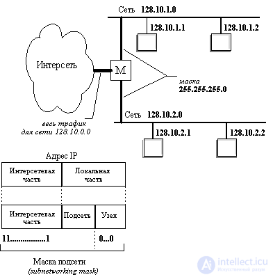
Fig. 4.4. Пример использования масок для структурирования сети
It should be noted that if a decision is made to use the mechanism of masks, then both routers and network computers must be configured accordingly.

Comments
To leave a comment
Computer networks
Terms: Computer networks