Lecture
Acousto-optic deflectors and scanners are devices for controlling the direction of a light beam in space. Scanners are designed for continuous beam sweep; the deflector has a set of fixed directions along which the light beam must deflect. In a diffraction deflector (Fig. 1), a beam of light falls on an AOS in which a sound wave of frequency f is excited and, as a result of Bragg diffraction, is partially deflected. As f changes, the angle of deflection of the diffracted beam also changes, and the beam moves along the screen of the photoreceiver. Using frequency-modulated audio signals allows you to control the direction of the light beam. In order to change the direction of a diffracted beam with a constant angle of incidence of light on AOJ, it is necessary to simultaneously change the direction of propagation of the sound wave, so that the Bragg condition is fulfilled everywhere inside the interval  sound frequencies - so-called. bandwidth deflector. determines other parameters of the device: the maximum angular displacement of the beam of diffracted light

and resolution N, i.e. the number of distinguishable positions of the light beam within  . The resolution is determined by and angular divergence
  light beam:
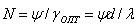
where d is the transverse size of the light beam. An important characteristic of spatial beam control devices is also the diffraction efficiency.  the ratio of the intensity I1 of the deflected light to the intensity I2 of the incident. In the simplest case, Bragg conditions are satisfied due to the divergence of the acoustic beam. The diverging beam can be considered as a set of plane waves, the wave vectors of which lie within the angular interval
  . For a given sound frequency f, diffraction will occur only on that component of the beam, for which the wave vector satisfies the Bragg condition. As f changes, another condition of the beam satisfies this condition. When using isotropic material as a working fluid where D is the transverse size of the sound beam,
  - sound wavelength. According to this bandwidth and the resolution N is proportional to the divergence of the acoustic beam:
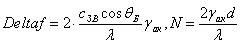
For a high-resolution deflector, a significant divergence of the sound beam is required, and, consequently, its minimum width is D. Reduced efficiency  caused by a decrease in the length of the acousto-optic interaction, is compensated by an increase in the input acoustic power. However, with increasing N, the efficiency of using this power decreases, since only 1 / N of its power is spent on the diffraction of light. The use of birefringent materials in OJA can significantly improve the characteristics of the deflectors. For this purpose, anisotropic diffraction of light near the imaginary Bragg angle value is used.
  . When the light falls on the sound beam at an angle the small divergence of the sound beam ensures that the Bragg condition is satisfied for a sufficiently wide range of acoustic frequencies, and, consequently, a considerable interval of angles of deflection of the diffracted light. This allows you to use a wide acoustic beam, which reduces the acoustic power required to obtain high diffraction efficiency , and gives a significant gain in resolution compared to deflectors that use isotropic materials. However, the operating frequencies of such devices usually lie in the gigahertz range. You can control the diffracted beam using the so-called. a phased array of emitters — a step system of phase-shifted transducers, the parameters of which are chosen so that the wave front corresponding to the center frequency of the passband is parallel to the plane of the individual transducer, and as the frequencies change, the front would rotate so as to compensate for the corresponding Bragg angle increment. This method of sound excitation allows to increase the bandwidth and resolution of the deflectors several times. There are acousto-optic deflectors that perform two-coordinate deflection of the light beam. In this case, two crossed one-dimensional deflectors are used, which can be combined in one acousto-optic cell, if acoustic waves are excited in it in two mutually perpendicular directions. Modern deflectors allow you to receive
  solvable elements with a transition time from one element to another order with. The proportion of deflected light reaches several tens of percent with an acoustical power consumption of 0.1-1 W. In devices based on acousto-optic refraction, the light beam is deflected as a result of the curvature of its path as it passes through an environment in which inhomogeneous deformation is created by a standing or traveling sound wave. Such devices are relatively low-frequency devices (
  MHz), carrying out the sweep of the light beam in a sinusoidal law. The efficiency of refractive devices is small, since only an insignificant part of the sound energy contained in the AOI volume is expended on the deflection of the light beam.
Acousto-optic modulators are devices that control the intensity of light beams based on the redistribution of light energy between transmitted and diffracted light. Typically, modulated diffracted light is used, since 100% modulation of transmitted radiation requires significant acoustic power.
Acousto-optical filters are devices that allow to distinguish a rather narrow interval of lengths of light waves from a wide spectrum of optical radiation that satisfy the Bragg condition. By changing the frequency of the sound, it is possible to move the allocated interval over the optical spectrum over a wide range.
Acousto-optic processors. Acoustic-optic instruments, discussed above, serve as the basis for creating microwave signal processing devices - the so-called. processors, which, unlike digital computers, allow for the processing of information in real time. In an acousto-optic processor, a time-varying electrical signal is converted by an electro-acoustic transducer into an ultrasonic wave, which, propagating into AOS, creates a spatial sound image of the signal. When light is diffracted by an audio signal, an optical image of the signal arises in the diffracted radiation, which is then processed using various optical elements: lenses, mirrors, diaphragms, transparencies, etc. The signal is processed by simultaneously reading all the information stored in the sound pulse. Acousto-optic processors perform a fast, in real time, Fourier decomposition of the microwave signal, frequency filtering of the signal, finding the correlation function of the signal under investigation with a given one, and other operations.
Acousto-optical correlator is designed to find the correlation function of two signals of the studied S (t) and reference r (t):
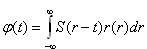
Acousto-optical filters are devices that allow the isolation of a correlator from an action based on the optical multiplication of images of these signals. The light in an acousto-optic modulator, diffracting on the sound wave modulated by the signal S (t), forms an optical image of this signal. Next, the diffracted light passes through a spatial filter, the transmission of which varies according to the law r (x) and is collected on a photodetector device, the output of which produces a signal proportional to the correlation function  . A second acousto-optic modulator can be used as a spatial filter, in which ultrasound waves are modulated by the signal r (t).
Read more about instruments based on acousto-optic effect you can read here:
- Balakshiy V.I., Parygin V.N., Chirkov L.E. Physical basics of acoustooptics. - M .: Radio and communication, 1985. - 280 s;
- http://www.electronics.ru/issue/2004/6/23

Comments
To leave a comment
Acoustoelectronics and acoustooptics
Terms: Acoustoelectronics and acoustooptics