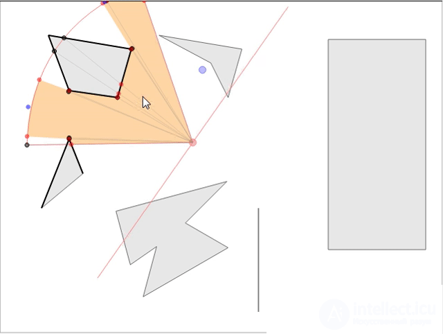
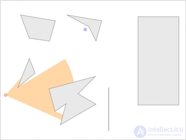
In strategic games it is usually required to know the scope of the NPC so that the player can think through the strategy and make the next move. We consider the mathematics and the implementation of a rational model that does not squander the speed of the game with a large number of NPCs on the map. If you want to see the finished interactive demo model, go here and play right in the browser! Here is a screenshot of the demonstration:
Having the parameters of visibility of the observer (direction of sight, distance of visibility and angle of the field of view), we need to find the area visible to him, i.e. determine the field of view (FoV). If there are no obstacles, it will be a sector of a circle consisting of two faces (radii) and an arc connecting them (see Fig. 1). In addition, having a given point of the world, we must quickly determine whether it is visible to the observer, i.e. it is necessary to process line of sight requests (line of sight, LOS) for a given point. Both of these operations can be performed quite effectively for use in real-time rendering.
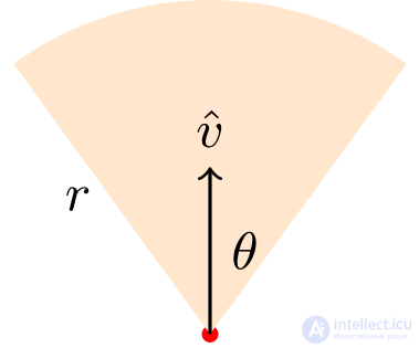 Fig. one
 The position of the observer is represented by a red dot, the arrow indicates the direction of gaze,
r is the distance of visibility, and
θ is half the angle of the field of view.
1 Input
- A set of polygons, including the borders of the world
- FoV parameters
- Observer position
- Direction of view, V
- Field of view, 2θ <180 °
- Distance of visibility r
Note: here and below, lowercase letters represent scalar values, and uppercase vector characters.
1.1 Polygons and edges
When describing the world in 2D, buildings naturally break up into polygons and thus become input to the algorithm. However, technically, the field of view is limited to the walls, i.e. edges of polygons. In addition, working with edges of polygons provides improved detail and control, because when checking intersections, we will mainly deal with geometric primitives. Therefore, in most cases, the algorithm works directly with the edges and does not apply to higher-level abstractions (polygons).
2 Basic algorithm
The first interesting idea that comes to mind is cropping the sector of visibility by the contours of polygons. But we consider the appearance, and an attempt to solve this problem by cutting along the contour will not work, the end result will be wrong. This is understandable, because the trim only cuts off the intersection of two areas, and for visibility we need to cut off not only the intersection, but everything behind it according to the principle of radiality. In Fig. 2 shows the result of trimming (left) and the expected result for this configuration (right).
 Fig. 2
 In the real world, we see objects when light rays freely enter the eye. It is intuitively clear that visibility can be defined by the inverse operation, i.e. Beaming from the eye into the world. In the case of a light source, rays are emitted in all directions. In practical implementation, rays are emitted radially at a predetermined interval, for example, one beam every 5 ° and 72 rays for the entire circumference. The beam should move until it is blocked by an edge. The emission of rays on all 360 ° and the determination of the region illuminated by the light source in 2D is a solved problem [1]. The accuracy of this method depends on the interval between the emitted rays. Shorter intervals provide greater density distribution of the rays.
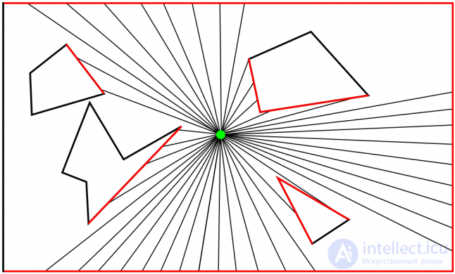 Fig. 3
 The emission of rays is, in other words, a check for the intersection of rays with segments of straight lines. For a given ray with m segments, m checks are performed to determine the edge nearest to the beam that blocks it. Therefore, in any ray tracking algorithm, to emit n rays per m edges, n × m checks must be performed. However, no matter how small the resource-intensiveness of checking the intersection of rays and straight segments (edges), in an enormous world with many light sources such an approach can become too costly.
Let's call the beam
blocking edge
blocking edge . In Fig. 3, they are highlighted in red. The point at which the ray intersects the blocking edge is called
the hit point . After finding all the points of impact they must be circularly connected, i.e. all points of contact are ordered by angle and are connected by lines to determine the area illuminated by the light source. The result will be an incorrect closed loop. It should be noted that when connecting the intersection points in this way, some corners or parts of the polygons are cut off, which leads to an incorrect or less accurate illuminated area. It can be improved by reducing the emission interval of the rays. The smaller the interval, the more rays and better coverage. The result is improving, but at the cost of reduced productivity.
With this problem of determining the illumination area, we examined the main approach that we will use to solve our problem: the ray casting method. Notice that the rays of light emanate from the light source in all directions until they intersect with the obstacle. The absence of restrictions makes the problem simpler compared to our problem, in which the angle and distance of visibility are limited. We will discuss why this is the case later in section 3.
2.1 Optimization
Instead of emitting rays in all directions (at a certain interval), the task is usually optimized by emitting rays only in those directions in which the edges of the edges are located. This significantly reduces the number of intersection checks required. The above n value should be less. Another advantage of this method is greater accuracy: now, for the accuracy of the designated scope, we do not rely on the selected interval.
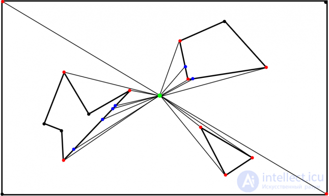 Fig. four
 We will call these edges of the edges, which give us the angle of emission of rays, the corner points. This name may instead seem redundant and meaningless, but later it will be useful to us. Corner points are points at which rays of visibility are emitted. In Fig. 4 corner points are marked in red, blue and black. Rays are emitted to all these points. Points closest to the beam are converted to hit points marked in red. The points that their ray does not reach are marked with black. These rays intersect with the closer edges and create hit points marked with blue.
2.2 Vision without angles
Although emitting rays only at the ends of the ribs suits us, it has a slight drawback. Notice in Fig. 4, the beam emitted to the corner of the polygon intersects one of the edges that create the angle, and does not move further. However, visibility should in some cases be beyond the angle. A clever approach to solving this problem is shown in an interactive article [2].
The idea is to divide the primary beam (the beam at the end of the edge) into two auxiliary ones, rejecting them by the angle “iota” clockwise and counterclockwise. If visibility should extend beyond the corner, one of these auxiliary rays will pass through the corner, thus determining the visibility behind it. The disadvantage of this approach is: instead of one beam, we now need to emit three for each corner point, which affects the speed three times more. It would be nice to minimize the number of corner points we need to process.
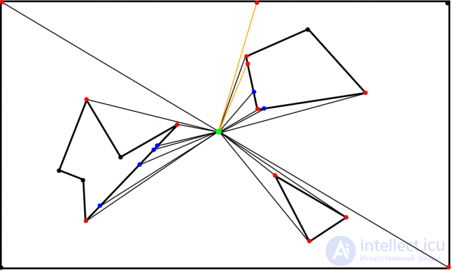 Fig. five
 Auxiliary rays highlighted in orange. The angle of deviation (between the orange and the black beam) is intentionally exaggerated here for clarity, but it should be much less than, say, half a degree.
A simple optimization would be to determine whether both edges are forming the corner, or one of them is hidden by the other. If both are visible, then the auxiliary rays are not required, because the visibility cannot extend further. In Fig. 4 the apex of the triangle is the visible angle, the auxiliary rays are not needed here, because the visibility cannot extend further. Auxiliary rays are needed only when one of the two edges is hidden from the observer. Both edges cannot be hidden, because we look at each corner of the polygon separately - at two edges and the point at which they connect (see Fig. 6, black arrows and blue point). Even if one of the edges is hidden, the emission of two auxiliary rays is redundant; one can be avoided because only one can pass around the corner without difficulty. In Fig. 5 the auxiliary beam created by rotating the primary clockwise is redundant.
 Fig. 6
 To determine whether one of the edges is blocking the other, one can use the split axis theorem. Projecting the vectors of both edges on a vector perpendicular to the primary ray will produce results with different signs if one of the edges blocks the other. Also, depending on the sign of the projection of the first edge, we can find out which of the two auxiliary rays is necessary. In Fig. 6 above shows three possible situations, and below - the results of the projection. The black dot indicates the position of the observer from which the primary beam is emitted (red). Rib vector vectors (black) are projected onto the perpendicular to the primary vector (green). If auxiliary rays are not required, both projections give negative values, because both edge vectors are in the negative half-space of the perpendicular. In two other cases where auxiliary rays are needed (orange), the signs of the projections differ from the signs of the vectors; if the sign is negative for a vector of a longer edge, then the auxiliary ray is sufficiently rotated clockwise, and if it is positive, then the ray rotated counterclockwise is sufficient.
3 Blocking edges and corner points
In the problem under consideration, visibility is limited by angle and distance; This leads us to interesting situations.
- Corner points are not all the ends of the edges, but only in the area of the sector of visibility.
- This at least halves the amount of rays emitted. n now becomes even smaller.
- To take advantage of this, efforts should be made to separate the corner points from the edges of the ribs. The technique used for this should be fast enough so that the separation itself does not take too long.
- In addition, most of the edges will not potentially block; for us, only those that are contained in the sector or are cut off by it are important.
- This reduces the number of required intersection checks. The value of m should decrease.
- For this purpose, we should also come up with a fast algorithm for cutting off unnecessary edges.
The main difference or deviation from the basic algorithm, explained in Section 2, is that there may be corner points that are not included in the set of edges of the edges. It may be necessary to determine more angular points. See configurations in Fig. 7 and 8. The edges of the edges are outside the sector of visibility, therefore they are useless as corner points. All corner points necessary for the correct definition of the scope (marked with black, blue and red) do not coincide with the ends of the edges. Each of them is necessary, the impossibility of emitting a beam into any of them will lead to an incorrect definition of the scope. How do they differ and how to define them?
Since vision is limited to the angle of sight, two corner points are necessary and must be unconditionally accepted regardless of the presence of an edge. They are extreme points on the edges of the sector. They emit rays and define the points of impact. In Fig. 7, black shows one of these implied corner points: a corner point arising from a point on the right edge of a sector. The beam emitted into it is blocked by an edge, which led to the appearance of a blue dot. Another beam emitted at the corner point of the left edge passes unobstructed. Therefore, the point of impact becomes the corner point itself, highlighted in blue. So, blue dots are easy to determine, they do not require checks. Their position is constant and depends on the position and direction of the sector of visibility.
Consider a red corner point (turned into a hit point, because the beam is not blocked by anything) at the intersection of the arc and edge of the sector. It requires another check of the intersection: checking the intersection of the arc and the line segment. These corner points are necessary when the edge intersects the arc of a sector.
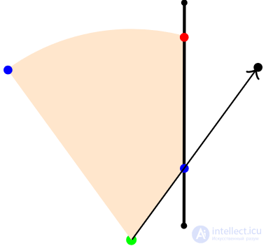 Fig. 7
 The beam is shown with the point of the arrow, and the edge has end points.
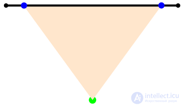 Fig. eight
 Taking this into account, we will list the occurrence of corner points:
- Any endpoint of the edge that is in the sector of visibility.
- Any point of the arc sector in which it intersects the edge
In addition, potentially blocking edges are edges that are fully or partially located in the sector.
Now the problem becomes the task of obtaining a set of corner points (searching for new ones and discarding unnecessary end points) and a set of potentially blocking edges (cutting off non-blocking edges). This task must be carried out quickly, discarding the wrong elements as early as possible so as not to burden the processing cycles with results that will be discarded later. The goal is to reduce the values of n (the number of emitted rays = the number of corner points) and m (the number of segments to check for intersection with the beam = the number of potentially blocking edges), which provides a fast algorithm for determining FoV.
3.1 Clipping
In [3], it is assumed that the ideal cut-off algorithm (in reality, it will be resource-intensive and complicated by the problems of floating-point accuracy) leaves only a lot of visible points, and a reasonably good algorithm discards most of the invisible ones, leaving exactly visible and potentially visible. It will be conservative when dropping potentially visible points. In other words, if he cannot be completely sure that the edge
does not interfere with visibility, he will
not discard it.
3.1.1 Early, trivial drop stage
The simplest idea for discarding unsuitable end points and edges is to check only the end points of the edges that are inside the sector. This is suitable for corner points, but not enough for blocking edges, because it does not work in configurations where the end points of the edges are not in the sector, but the edge blocks visibility (see Fig. 7 and 8). Before proceeding to a more detailed analysis, the endpoint check can be completely skipped if we can drop the edge.
3.1.1.1 Intersection of an edge with a bounding circle
If the segment point closest to the center of the circle is inside the circle, then it either lies in it or intersects it. This approach is described in detail in [4]. With the help of the edge and the bounding circle of the sector, we can discard all edges that are not included in the bounding circle. After this stage, all edges that are not in a circle are not considered. Since this is not a test for searching for intersection points, but simply cutting off extra edges, the result is represented in Boolean form and is obtained rather quickly. To implement this test, we need only a couple of vector subtraction operations (giving a vector) and scalar products: one to find the nearest point (by projection), and another to calculate the square of the distance from it to the center of the circle.
The results of this check are shown in Fig. 9. The bounding circle of the visibility sector is marked by a dotted line. The blue dot on each edge indicates the point closest to the center of the circle. Green edges are saved for further calculations. Lilac also persist, but are false positive. Red discarded. The edge on the bounding circle is also dropped, because it does not interfere with visibility.
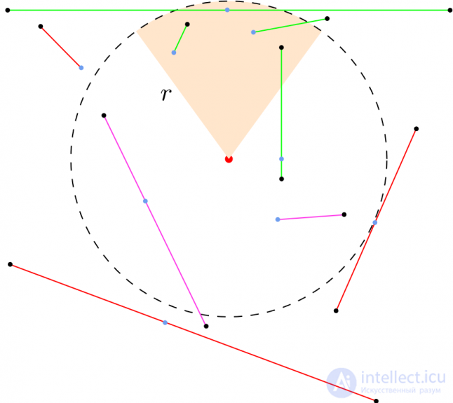 Fig. 9
 For aggressive rejection of false-positive results, the idea of checking the nearest point in the sector, and not in a circle, looks attractive. However, such a test is incorrect, because it will discard positive results. In Fig. 9, along with the purple dots, the green edge will also be dropped, the nearest point being outside the sector.
3.1.1.2 Point relative to the sector
Having a point and a sector, you can quickly determine
- is the point behind the observer
- in front of the observer and
- out of sight
- within sight distance and
- inside the sector
- outside the sector but inside the limiting semicircle
using only scalar and vector products. Since the vector product is not defined in 2D, we transfer the vectors to 3D, taking z = 0. The results of the vector product are vector, but since z = 0, the elements related to x and y will be equal to 0, and only the value z will be nonzero ( если векторы непараллельны).
Thus, we obtain a scalar result from this vector product. See the various definitions of a vector product in 2D in [5]. Let the vector from the center of the circle to the point be (U), and the vectors of the sector edges be E1, E2. We already have the direction of view V.- If U ⋅ V <0, then the point is behind the observer.
- otherwise, if U ⋅ U = ‖U‖ 2 > r 2 , then the point is out of sight.
- otherwise, if sign (E1 × U) = sign (U × E2), then the point is in the sector.
- otherwise it is in the surrounding semicircle, but outside the sector.
We used two optimizations that required explanations. We compare the squares of lengths (2) instead of the comparison of lengths, because finding the length means using
sqrt (квадратного корня) . We avoid this and apply the optimization that is customary for working with computer graphics ([7]). To check whether a point is inside a sector (3), we can find the angle opposite the first edge of the sector and check whether it is inside the allowable angle of visibility (2θ). However, for this you need to use the
acos (арккосинус) trigonometric function, which may be more expensive than calculating a pair of vector products that uses only arithmetic operations.
If the edge “survived” the previous check, we check its endpoints to determine where they are located. In Fig. 10 shows the current situation: gray points behind the observer (1), red - outside the sector (2), green endpoints - inside the sector (3), and lilac - inside the bounding semicircle, but outside the sector (4).
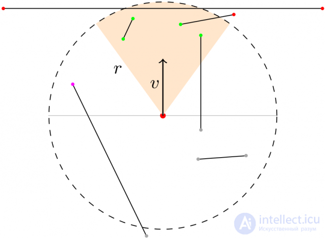 Fig. ten
 Corner points and blocking edges can be determined from the results:
- If both ends of the observer (1), they do not interfere with visibility; discard them and no longer handle.
- If both ends are inside sector (3), mark both as corner points, and edge as blocking. We stop further processing.
- If one of them is inside a sector (3), and the other is not - (1), (2), (4) - we mark one inside as a corner point, and an edge - as a blocking one. This edge can intersect the sector arc and create a new corner point.
- If both are outside the sector - (2), (4) - the end points are not angular, but the edge can intersect the sector arc, creating new corner points. An edge can be blocking if it intersects an arc or sector edges.
In cases 3 and 4, we need additional checks to find corner points that are not end points contained inside the edges and block visibility by the edges. This leads us to the stage of narrowing the cut.
3.2 Contraction Stage
At this stage, we get rid of other false-positive results with more costly checks to improve the performance of the emission of rays. We can carry out checks on the intersection of the edge and arc of an arch and / or edge and edge.
However, before performing a little costly verification of the intersection of a segment and an arc (it uses a square root and more than three branch operations), we can use the results of the previous verification to make sure that verification is necessary. The check is needed only when the edge has the ability to cross the arc. If both endpoints are inside a bounding circle, the edge will not be able to cross the circle. An edge can cross an arc of a sector only if one of its end points is in front of the observer, and the other is outside the bounding circle (case 2.1 in section 3.1.1.2).
Table 1. Possible positions and states of the end points of the edges | No | End A | End B | condition |
|---|
| one | Inside | Inside (2.2.1) | Corner points: A, B • Blocks |
| 2 | Inside | Rear (1) | Corner Point: A • Blocks |
| 3 | Inside | In the semicircle (2.2.2) | Corner Point: A • Blocks |
| four | Inside | Outside (2.1) | Corner point: A • Blocks • may cross the arc |
| five | Behind | Behind | Discarded |
| 6 | Behind | Outside | Can cross an arc • can block |
| 7 | Behind | In the semicircle | Can block |
| eight | In the semicircle | In the semicircle | Can block |
| 9 | In the semicircle | Outside | Can cross an arc • can block |
| ten | Outside | Outside | Can cross an arc • can block |
We have already dealt with points 1, 2, 3 and 5 at the stage of early discarding, and we do not need to do anything with them. Point 4 requires checking the intersection of the edge with the arc to ensure that no additional corner point is needed. At an early stage, we have already marked one of its end points as a corner point, and an edge as a blocking point. Points 6-10 are the most interesting at the stage of narrowing. For points 6, 9, and 10, we need to check the intersection of the edge with the arc in order to know if corner points appear at the intersection. If so, the edge should be marked as blocking. If these points do not pass the test, they join points 7 and 8. They cannot have corner points, but they still have to go through the edge and edge intersection check in order to know if they are blocking visibility.
3.2.1 Intersection of the edge and arc sector
For points 4, 6, 9 and 10 of Table 1, by checking the intersection of the segment and the arc, we check whether the edge intersects the sector arc [6]. If this is the case, then we mark the intersection points as corner points, and the edge as blocking. Further processing is not required. If this is not the case, the edge cannot have corner points, but the edge must pass the following visibility blocking test.
In essence, this is a check of the intersection of a line and a circle, the result of which are two points. Points lying on the segment and on the arc are considered the points of intersection. Here you can make a small optimization: if both intersection points are behind the observer, then the segment cannot block the visibility and have corner points, so the edge can be dropped without further processing.
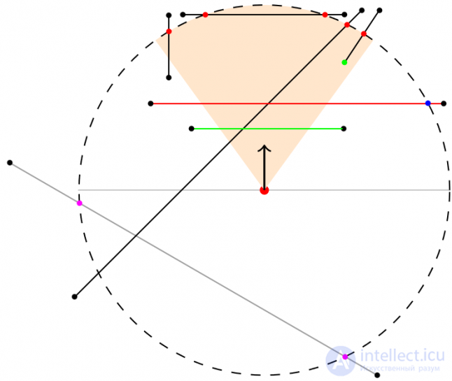 Fig. eleven
 In Fig. 11 a gray edge is checked with one end point out of sight, and the other end point is checked behind the observer, but both intersection points behind the observer (lilac) and, therefore, are discarded. A green edge with both points in a semicircle is never checked. The red edge with one end point out of sight is checked, but the only intersection point found (blue) is not on the arc. This edge cannot have corner points, but is sent to the next stage (checking the intersection of the edge and edge) to check for a blockage. All other edges (black) with one or both end points outside the bounding circle, having suitable (red) intersection points are marked as blocking, and intersection points as corner points. Each such edge corresponds to one of points 4, 6, 9 or 10 in Table 1.
3.2.2 Intersection of the edge and sector edge
For points 7 and 8, which have never passed the previous check, and for points (6, 9 and 10) that passed the check, which did not find any intersection points, there can be no corner points on the edge. Both of its end points are not inside the sector, and no new corner points lie on the arc. However, such edges cannot be rejected, because they can still block (see Fig. 8) or not block (see Fig. 10; an edge with a purple end point). We have two options: make sure and mark them as blockers or check their intersection with sector edges to be sure. Choosing the first option, for each false positive intersection with the sector of visibility, we pay checks by the intersection of the segment and segment n at the stage of emission of rays, because each beam is checked for intersection with each potentially blocking edge. Instead of paying n times for false positive results, the best option would be to spend n + 2 (in the worst case). Therefore, we check the edge for intersection with both edges of the sector. If an edge intersects at least one of them, we mark it as blocking.
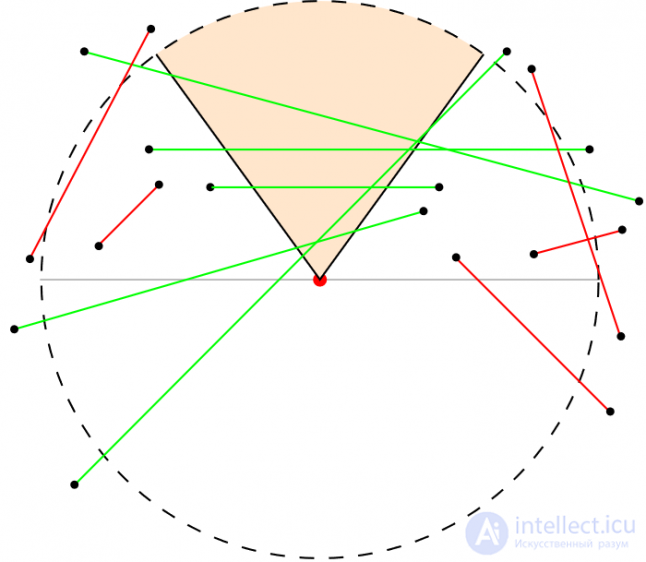 Fig. 12
 For items 6-10 in Fig. 12 there are two corresponding edges: one positive (green), the other negative (red). From the figure it is obvious that this check has a greater probability of dropping edges that do not correspond to the visibility.
4 Beam emission
We have all the corner points and blocking edges. Before performing ray tracking, it is necessary to sort the corner points by angle so that the final shape of the scope is correct when connecting the points of hitting by edges and arcs. In addition, if two or more corner points and the position of the observer are collinear, then several rays will be emitted in one direction. It is necessary to discard the duplicate corner points in order to avoid extra rays.
For sorting technique can be used. described in section 3.1.1.2: using the vector product to determine whether a point is inside the visibility sector. Duplicate corner points can be easily processed again using a vector product. Before a beam is emitted for each corner point, it multiplies vectorially with the previous one, and if the result is zero, then the vectors are linearly dependent (parallel), which means that they can be ignored.
Primary rays are emitted at sorted corner points. If we know that the point is the end point of the edge, and not the intersection point, then it is also necessary to emit auxiliary rays (for more details, see Section 2.2). Auxiliary rays are emitted only at the corner points, which are the end points of the edges, and are not emitted at the intersection points, because they cannot be the corners of the polygons, i.e. visibility cannot extend beyond them.
For each emitted beam, we find the point of intersection of the beam and the nearest edge to it. It becomes the point of impact of the beam. If this point is outside the visibility distance r, then we take the hit point as a point along the ray, which is at a distance r from the observer. Those. we drag the hitting point backward until the distance from it to the observer becomes equal to r. We check whether each hit point is at the edge of the arc. If this and the previous point is on the border of the arc, then we connect them with an arc, and otherwise - with a segment. However, when performing this task "blindly" there is a small problem.
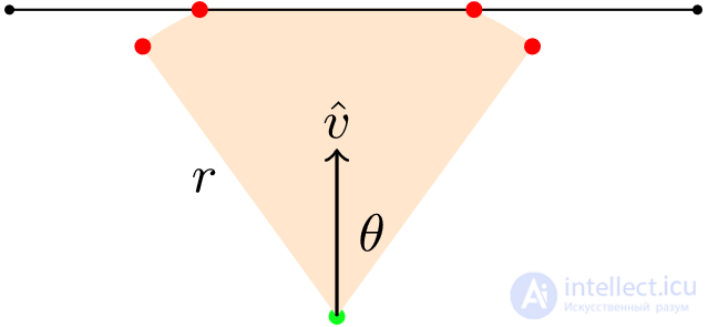 Fig. 13
 In Fig. 13 points of impact (numbered from right to left) 1 and 2 are on the arc, and must be connected by an arc. The same is the case with the points of entry 3 and 4. However, the points of entry 2 and 3 must be connected by a segment, because there is an edge intersecting an arc. If a hit point 3 is detected and it is confirmed that it and the previous hit point are on an arc, before connecting them with an arc, check whether the connecting line is parallel to the nearest edge on which the hit point lies 3. Connect them with a segment if they are parallel.
5 Line of sight
A line of sight request is needed to answer the question of whether a certain point in the world X is visible to an observer with given observer parameters (see section 1). After finding the blocking edges and corner points, this is easy to do. First, we classify X according to section 3.1.1.2. If the point is not inside the sector, we return false . If it is inside, we check if any of the blocking edges intersects the segment formed by connecting X with the observer. If it does not intersect, we return true , because the line of sight or the beam from the observer to the object does not interfere. Accordingly, the object is visible.

Comments
To leave a comment
Computer games developming
Terms: Computer games developming