Lecture
The assembly language allows a programmer to use text mnemonic (that is, easily remembered by a person) codes , at its discretion, assign symbolic names to computer and memory registers, as well as set convenient ways of addressing . In addition, it allows you to use different number systems (for example, decimal or hexadecimal) to represent numeric constants, use comments in the program, etc.
Programs written in assembly language require significantly less memory and runtime. A programmer’s knowledge of assembly language and machine code gives him an understanding of machine architecture. Despite the fact that most software specialists develop programs in high-level languages, such as Object Pascal or C, the most powerful and effective software is written in whole or in part in assembly language.
High-level languages were developed in order to free a programmer from taking into account the technical features of specific computers and their architecture. In contrast, assembly language is designed to take into account the specific specifics of the processor. Consequently, in order to write a program in assembly language for a specific computer, it is important to know its architecture [57].
As an example, we present an assembly language program for the IBM PC. The program calculates the value of a = b + c for a, b and c integers:
.MODEL SMALL .DATA b DW 5 c DW 3 a dw? .CODE begin MOV AX, @ DATA MOV DS, AX MOV AX, B ADD AX, C MOV A, AX MOV AH, 4CH INT 21H END begin |
The .MODEL directive specifies the mechanism for allocating memory for data and commands. The .DATA directive defines the beginning of a program section with data. DW directives specify the types of variables and their values. The .CODE directive defines the beginning of a program section with commands. The MOV AX, @ DATA and MOV DS, AX commands write the address of the data segment to the DS (Data Segment) register. To calculate a, the commands MOV AX, B, ADD AX, C and MOV A, AX are used. In the END directive, the label of the first program's begin program to begin is set. |
Translation of a program from assembly language to machine language is carried out by a special program, which is called an assembler and is, in fact, the simplest translator.
Assembly language concept
Program segments, subroutine segments
Code representation of commands
Memory addressing
There are several versions of the program assembler. One of the most commonly used is the Turbo Assembler package, which is part of the Borland Pascal 7.0 software package. Consider working with this package in more detail.
The input information for the assembler (TASM.EXE) is the source file - the text of the program in assembly language in ASCII codes. As a result of the work of the assembler, you can get up to 3 output files:
There are many ways to specify assembly names for files. The first and easiest way is to invoke the command with no arguments. In this case, the assembler itself queries the file names one by one: input (just enter the file name without the ASM extension), object, listing, and cross-reference file. For all queries, there are default modes, if in response to a query, press the Enter key:
If the assembler detects errors during assembly, it writes messages about them to the listing file. In addition, he displays them on the display screen.
Another way to specify assembly names for files is to specify them directly on the command line, separated by commas when calling the appropriate program, for example:
TASM Test, Otest, Ltest, Ctest
In this case, the first is the name of the source file, then the object, listing, and finally, the cross-reference file. If any name is omitted, then this is instructed by the assembler to generate the corresponding file according to the standard naming convention.
The program resulting from the assembly (object file) is not yet ready for execution. It needs to be processed by the TLINK link editing command, which can link several different object modules into one program and form an executable load module based on the object module.
The input information for the TLINK program is the names of the object modules (files are specified without the OBJ extension). If there is more than one file, then their names are entered through the separator "+". The modules are connected in the same order in which their names are transferred to the TLINK program. In addition, TLINK requires the name of the output executable to be specified. By default, it is assigned the name of the first of the object modules, but with the extension EXE. By entering a different name, you can change the file name, but not the extension. Then you can specify the file name for storing the map of links (by default, the map is not generated). The last thing that is indicated to the TLINK program is the libraries of the programs that can be included in the module obtained during the linking. There are no such libraries by default.
TLINK prompts for information about all these files from the user after calling it.
Graphically, the process of creating a program in Assembly language can be represented as shown in Figure 3.1.

All assembly programs consist of one or more sentences and comments. The sentence and comments are a combination of characters in the alphabet of the language, as well as numbers and identifiers, which are also formed from the characters of the alphabet. The alphabet of the language consists of numbers, lowercase and uppercase letters of the Latin alphabet, as well as the following symbols:
? @ _ $:. [] () <> {} + / * &%! '~ | \ = # ^; , `"
Assembly language constructs are formed from identifiers and terminators. An identifier is a set of letters, numbers and symbols "_", ".", "?", "$" Or "@" (the symbol "." Can only be the first character of the identifier) that does not begin with a digit. The identifier should be completely located on one line and can contain from 1 to 31 characters (more precisely, only the first 31 characters of the identifier are significant, the rest are ignored). From each other identifiers are separated by a space or a delimiter, which is considered to be any invalid character in the identifier. The following program objects are represented by identifiers:
Variables identify stored data. All variables have three attributes:
A label is a special case of a variable when it is known that the memory it defines contains machine code. It can be referenced via transitions or calls. The label has two attributes: SEGMENT and DISPLACEMENT.
Names are characters defined by the EQU directive and having a value character or number. The values of the names are not fixed during the assembly process, but when the program is executed, the names correspond to constants.
Some identifiers, called keywords, have a fixed meaning and should be used only in accordance with this. The key words are:
In identifiers, the same lowercase and uppercase letters are considered equivalent. For example, the identifiers AbS and abS are considered coincident.
The following describes the types and forms of data representation that can be used in expressions, directives and instructions of assembly language.
Integers have the following syntax (xxxx - numbers):
[+ | -] xxxx
[+ | -] xxxxB
[+ | -] xxxxQ
[+ | -] xxxxO
[+ | -] xxxxD
[+ | -] xxxxH
The Latin character (at the end of a number), which can be encoded in both registers, specifies the base of the number system: B is binary, Q and O are octal, D is decimal, H is hexadecimal. Hexadecimal numbers should not begin with alphanumeric characters (for example, 0ABh should be used instead of incorrect ABh). Hexadecimal digits from A to F can be encoded in both registers. The first form of the integer uses the default basis (usually decimal).
Character and string constants have the following syntax:
'characters'
"characters"
A character constant consists of a single character alphabet of a language. A string constant includes 2 or more characters. Unlike other components of a language, string constants are case-sensitive. The symbols "'" and "" "in the body of a constant must be encoded twice.
In addition to integer and character types, the assembler contains a number of other types (for example, real numbers, binary-decimal numbers), but their consideration is beyond the scope of this manual.
All modern programs are developed in a modular fashion - the program usually consists of one or several small parts, called subprograms or procedures, and one main program that calls these procedures for execution, transferring control of the processor to them. After completion of the procedure, control is returned to the main program and execution continues with the command following the subroutine call command.
The advantage of this method is the possibility of developing programs of much larger volume in small functionally complete parts. In addition, these routines can be used in other programs without having to rewrite parts of the program code. To top it all, since the size of a segment cannot exceed 64K, when developing programs with a code size of more than 64K, one simply cannot do without a modular principle.
The assembler programming language supports the use of two types of procedures - the near (near) and the far (far).
Near type procedures must be in the same segment as the calling program. A further type of procedure means that it can be accessed from any other code segment.
When calling a procedure, the return address to the calling program is saved on the stack:
In the general case, the group of commands that form a subprogram can be omitted in the program text. For convenience of perception, it is customary to draw up procedures in Assembly language in a special way. The procedure description has the following syntax:
PROC
ENDP
It should be noted that in the PROC directive there is no colon after the name, although the name is considered a label.
The parameter specified after the PROC keyword determines the type of procedure: short (NEAR) or long (FAR). If the parameter is absent, then the default procedure is considered to be near.
In general, you can place a subprogram in the program body anywhere, but remember that the subprogram itself should not be executed, but should be executed only when it is accessed. Therefore, it is customary to place subroutines either at the end of a code segment, after a program completion command, or at the very beginning of a code segment, before the program entry point. In large programs, subprograms are often placed in a separate code segment.
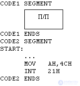
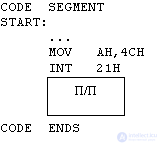
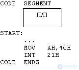
Fig. 1. Options for placing the subroutine in the program body.
You can transfer the actual parameters to the procedure in several ways. The simplest way is to pass parameters through registers: the main program writes parameters to some registers, and the procedure extracts them from these registers as necessary and uses them in its work. This method has one main drawback: you can transfer parameters through registers if there are few of them (if there are many, then there will simply not be enough registers). This problem can be solved by passing parameters through the stack. In this case, the main program writes the parameters to the stack and calls the subroutine, the subroutine works with the parameters and, returning control, clears the stack.
To work with subroutines, special commands are included in the processor command system; this is a call to the CALL subroutine and the return control RET.
All CALL call commands are unconditional. The NEAR CALL Intra Segment Call is used to transfer control to a procedure in the same segment. It specifies the new value of the IP register and stores the old value of the program counter (IP) on the stack as the return address. The FAR CALL intersegment call is used to transfer control to a procedure that is in another segment or even a software module. It sets the new CS segment and IP offset values for further program execution and saves both the IP register and the CS register on the stack.
All RET returns are indirect transitions because they retrieve the transition address from the top of the stack. The intrasegment return extracts one word from the stack and places it in the IP register, and the intersegment return extracts two words from the stack, putting the words from the smaller address into the IP register, and the word from the larger address into the CS register. The RET instruction can have an operand, which is a value added by the microprocessor to the contents of the stack pointer SP after retrieving the return address (clearing the stack).
A microprocessor command is a command that performs the required action on the data or changes the internal state of the processor.
There are two main processor architectures. The first is called RISC (Reduced Instruction Set Computer) - a computer with a reduced instruction set. The RISC architecture is named after the first computer with a reduced set of commands - RISC I. The idea of this architecture is based on the fact that the processor spends most of the time on executing a limited number of instructions (for example, transitions or assignment commands), and the rest of the commands are rarely used.
The developers of RISC-architecture created a "lightweight" processor. Thanks to the simplified internal logic (fewer commands, less complex logical circuits), the execution time of individual commands was significantly reduced and overall performance increased. The architecture of RISC is similar to a “communication architecture” with a dog — it knows only a few commands, but executes them very quickly.
The second architecture has a complex system of commands, it is called CISC (Complex Instruction Set Computer) - a computer with a complex system of commands. The CISC architecture involves the use of complex instructions that can be divided into simpler ones. All x86-compatible processors belong to the CISC architecture.
Let's consider the command “load the number 0x1234 into the AX register”. In assembly language, it is written very simply - MOV AH, 0x1234. By now, you already know that each team is represented as a binary number (clause 7 of the von Neumann concept). Its numerical representation is called machine code. The command MOV AH, 0x1234 in machine language can be written as:
0x11xx: previous command
0x1111: 0xB8, 0x34, 0x12
0x1114: the following commands
We put the team at 0x1111. The next command starts three bytes further, which means that 3 bytes are allocated for the command with operands. The second and third bytes contain operands of the MOV command. What is 0xB8? After converting 0xB8 to the binary system, we get the value 10111000b.
The first part, 1011, is the MOV command code. Upon encountering code 1011, the controller “understands” that it is MOV in front of it. The next digit (1) means that the operands will be 16-bit. The last three digits define the destination register. Three zeros correspond to the AX register (or AL, if the previous bit was O, thus indicating that the operands will be 8-bit).
To decode commands, the controller must first read them from memory. Suppose the processor has just finished executing the preceding instruction, and the IP (instruction pointer) contains the value 0x1111. Before processing the next command, the processor will “look” at the control bus to check if hardware interrupts are required.
Если запроса на прерывание не поступало, то процессор загружает значение, сохраненное по адресу 0x1111 (в нашем случае — это 0хВ8), в свой внутренний (командный) регистр. Он декодирует это значение так, как показано выше, и «понимает», что нужно загрузить в регистр АХ 16-разрядное число —- два следующих байта, находящиеся по адресам 0x1112 и 0x1113 (они содержат наше число, 0x1234). Теперь процессор должен получить из памяти эти два байта. Для этого процессор посылает соответствующие команды в шину и ожидает возвращения по шине данных значения из памяти.
Получив эти два байта, процессор запишет их в регистр АХ. Затем процессор увеличит значение в регистре IP на 3 (наша команда занимает 3 байта), снова проверит наличие запросов на прерывание и, если таких нет, загрузит один байт по адресу 0x1114 и продолжит выполнять программу.
Если запрос на прерывание поступил, процессор проверит его тип, а также значение флага IF. Если флаг сброшен (0), процессор проигнорирует прерывание; если же флаг установлен (1), то процессор сохранит текущий контекст и начнет выполнять первую инструкцию обработчика прерывания, загрузив ее из таблицы векторов прерываний.
К счастью, нам не придется записывать команды в машинном коде, поскольку ассемблер разрешает использо
Мы уже знаем, что адрес, как и сама команда, — это число. Чтобы не запоминать адреса всех «переменных», используемых в программе, этим адресам присваивают символические обозначения, которые называются переменными (иногда их также называют указателями).
При использовании косвенного операнда адрес в памяти, по которому находится нужное значение, записывается в квадратных скобках: [адрес]. Если мы используем указатель, то есть символическое представление адреса, например, [ESI], то в листинге машинного кода мы увидим, что указатель был заменен реальным значением адреса. Можно также указать точный адрес памяти, например, [0x594F].
Чаще всего мы будем адресовать память по значению адреса, занесенному в регистр процессора. Чтобы записать такой косвенный операнд, нужно просто написать имя регистра в квадратных скобках. Например, если адрес загружен в регистр ESI, вы можете получить данные, расположенные по этому адресу, используя выражение [ESI].
Теперь рассмотрим фрагмент программы, в которой регистр ESI содержит адрес первого элемента (нумерация начинается с 0) в массиве байтов. Как получить доступ, например, ко второму элементу (элементу, адрес которого на 1 байт больше) массива? Процессор поддерживает сложные способы адресации, которые очень нам пригодятся в дальнейшем. В нашем случае, чтобы получить доступ ко второму элементу массива, нужно записать косвенный операнд [ESI + 1].
Имеются даже более сложные типы адресации: [адрес + ЕВХ + 4]. В этом случае процессор складывает адрес, значение 4 и значение, содержащееся в регистре ЕВХ. Результат этого выражения называется эффективным адресом (ЕА, Effective Address) и используется в качестве адреса, по которому фактически находится операнд (мы пока не рассматриваем сегментные регистры). При вычислении эффективного адреса процессор 80386 также позволяет умножать один член выражения на константу, являющуюся степенью двойки: [адрес + ЕВХ * 4]. Корректным считается даже следующее «сумасшедшее» выражение:
[число - б + ЕВХ * 8 + ESI]
На практике мы будем довольствоваться только одним регистром [ESI] или суммой регистра и константы, например, [ESI + 4]. В зависимости от режима процессора, мы можем использовать любой 16-разрядный или 32-разрядный регистр общего назначения [ЕАХ], [ЕВХ],... [ЕВР].
Процессор предыдущего поколения 80286 позволял записывать адрес в виде суммы содержимого регистра и константы только для регистров ВР, SI, DI, и ВХ.
В адресации памяти участвуют сегментные регистры. Их функция зависит от режима процессора. Каждый способ адресации предполагает, что при вычислении реального (фактического) адреса используется сегментный регистр по умолчанию. Сменить регистр по умолчанию можно так:
ES:[ESI]
Некоторые ассемблеры требуют указания регистра внутри скобок:
[ES:ESI]
In our examples, we will assume that all segment registers contain the same value, so we will not use them when addressing.

Comments
To leave a comment
Programming Languages and Methods / Translation Theory
Terms: Programming Languages and Methods / Translation Theory