Lecture
When crossing the surface with a plane in cross section, a flat line is obtained. This line is built on separate points. At the beginning of the construction, first identify and build reference points lying on the contour lines of the surface, as well as points on the edges and lines of the base surface. In those cases where the projection of the intersection line is not completely determined by these points, additional, intermediate points located between the reference points are constructed.
This section discusses cases of intersection of the surface by the planes of a particular position, since in the case of the presence of a section plane of general position, the drawing can always be transformed so that the section plane becomes projecting (see Fig. 129).
In the case of the intersection of a face surface by a plane, a flat broken line is obtained. To build this line, it is enough to determine the intersection points of the edges and sides of the base plane if there is an intersection of the base, and connect the constructed points with regard to their visibility (Fig. 124, a). Since in this case the cutting plane E occupies the frontal projecting position, the points of intersection of the edges are determined without additional constructions:
AS ^ Sum = 1 (1 2 ; l 1 ); Sum = (2 2 ; 2 1 ); CS ^ Sum = 3 (3 2 ; 3 1 ).
Since the face ACS is invisible relative to the plane P \ , the line l 1 —3 1 is also invisible.
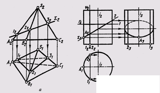
Fig. 124
In the case of intersection of a cylindrical surface of rotation by a plane, the following lines can be obtained (Fig. 124, b):
a circle, if the cutting plane is perpendicular to the axis of rotation of the surface;
ellipse, if the cutting plane Sum is not perpendicular and not parallel to the axis of rotation;
two forming straight lines if the secant plane U is parallel to the axis of the surface.
On the plane P 1 , perpendicular to the axis of rotation of the surface, the circle and ellipse on the surface of the cylinder are projected into a circle that coincides with the projection of the entire surface.
At the intersection of the conical surface of rotation by the plane, the following lines can be obtained (Fig. 125, a - e):
a circle, if the cutting plane F is perpendicular to the axis of rotation (a);
an ellipse, if the cutting plane Sum 1 intersects all forming surfaces (b);
parabola, if the cutting plane (Sum 2 ) is parallel to only one generator (S - 1) of the surface (c);
hyperbola, if the cutting plane (Sum 3 ) is parallel to two generators (S — 5 and 5-6) of the surface (g);
two generators (straight lines), if the section plane (Sum 4 ) passes through the vertex S of the surface (d). Projection of curved section lines
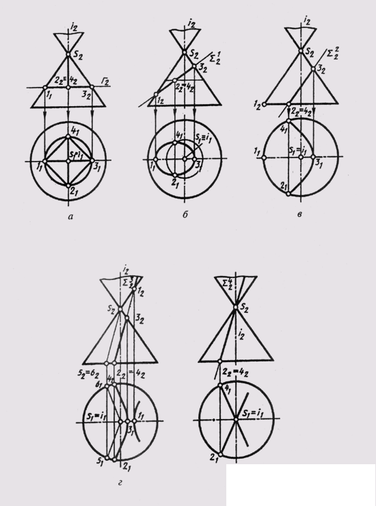
Fig. 125
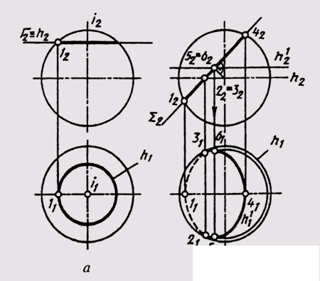
Fig. 126
the plane of the cone are built on individual points (points 2, 4 in Fig. 125, b).
When a plane crosses a sphere, a circle is always obtained. If the cutting plane is parallel to any plane of projections, then the section circle is projected onto this plane without distortion (Fig. 126, a). If the cutting plane occupies a projecting position, then on the plane of projections, to which the cutting plane is perpendicular (Fig. 126, b — on the frontal plane), the section circle is depicted as a straight line segment (1 2-4 4 ) whose length is equal to the diameter of the circle, and on the other plane - an ellipse, the major axis of which (5 1 —6 1 ) is equal to the diameter of the circumference of the section. This ellipse is built on points. Points of visibility 2 and 3 relative to the plane P 1 lie on the equator of the sphere.
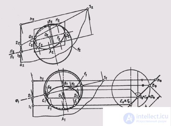
Fig. 127
The task of building an intersection line is somewhat more difficult when the sphere is crossed by a plane of general position (Fig. 127) Q (a ^ h ).
This case can be reduced to the previous one (see Fig. 126, b), if we construct additional images of the sphere and the cutting plane on the plane P 4 _ | _P 1 , and P 4 _ | _ h (6). Then the plane in will become projecting Q _ | _P 4 in the new system of planes (see. Fig. 127). In the drawing, the axes of the projection pass through the center of the sphere. On the plane P 4 we note the projections of the control points: A 4 - the lowest point of the section; 4 - the highest, giving the value of the diameter d of the circumference of the section with the center at the point O (O 4 ); Е 4 = F 4 - at the equator of the sphere - points of visibility of the section line relative to the plane П 1 , С 4 = D 4 = O 4 - the horizontal diameter CD, defining the major axis of the ellipse, - the horizontal projection of the section circle. The horizontal projection of the section — an ellipse — is easily constructed along the large C 1 D 1 and small A 1 B 1 axes. The frontal projection of the circle is also an ellipse, which can be constructed from conjugate diameters A 2 B 2 and C 2 D 2 (the heights of these points are marked on the plane P 2 and on the plane P 4 ) using the parallelogram described. The visibility of the section circle with respect to the plane P 2 is determined by the points G and H obtained at the intersection of the main meridian of the sphere f with the plane 9. For this, an auxiliary plane of level F is taken:
F e f ; Ф ^ Q = 2-3;
f 2 ^ 2 2 —3 2 = H 2 and G 2 .
The cut lines are obtained when the surface of rotation intersects a plane parallel to the axis of rotation of the surface. Cut lines are often found on parts surfaces. In fig. 128 a cut line of the complex surface consisting of the surfaces of the sphere and the cone, the frontal plane of the level F, is constructed. The cut line includes
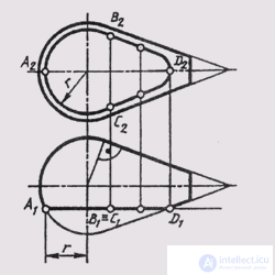
Fig. 128
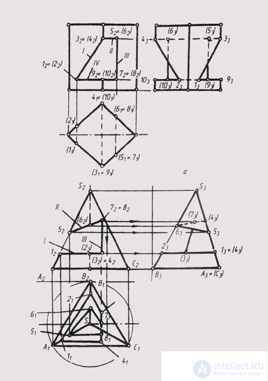
Fig. 129
the intersection of the sphere (В 2 - А 2 - С 2 ) is a part of a circle of radius r - and the line of intersection of the cone (B 2 - D 2 - C 2 ) is a branch of the hyperbola, which is built at individual points. As auxiliary cutting planes for constructing intermediate points, take planes that are perpendicular to the axis of rotation of the surfaces.
The intersection of the surfaces of geometric figures can be carried out not by one but by several cutting planes. As in the case of intersection with one plane, the construction of each intersection line is simplified if the section planes are private position planes.
In fig. 129, and for a given frontal projection of the notch, made in a regular triangular pyramid with three front-projecting planes, horizontal and profile projections were constructed. When solving such problems, first analyze the shape of each face of the cut. The sides of these polygons will be: 1) the lines of intersection of the faces of the pyramid with the planes of the notch and 2) the lines of intersection of the planes of the notch with each other. Vertices: 1) the intersection points of the edges of the pyramid with the planes of the notch and 2) the ends of the segments along which the edges of the notch intersect with each other. In fig. 129, and the plane I intersects the edges of the pyramid S A and SB at points 1 and 2, and intersects with the plane III along the segment 3-4; thus, the shape of the face 1 is a quadrilateral 1-2-3-4. Similarly, in plane II we get a quadrangle 5–7–7–8. The vertices of a quadrangle 3–4–8–7 in face III are the ends of the segments along which this face intersects with faces I and P. The sides of all these polygons are the outlines of the cutout. To obtain their projections on the square. P 1 and P 3 First you need to note the front projections (1 2 ... 8 2 ) of all the vertices, then build their horizontal and profile projections, and then connect them to P 1 and P 3 vertices of each polygon are consistent, taking into account the visibility of each segment. Face I is located horizontally, therefore on P 3 it is projected into a horizontal segment. The edge of the SAC pyramid is profile-projecting, so all the cut lines obtained in it are on P 3 projected in one line. When drawing a stroke, you need to erase or leave parts of the cut edges of the pyramid in thin lines.
In fig. 129, b are constructed projections of a regular quadrangular prism with a hole bounded by front-projection planes.
Each face of the notch (I, II, III, IV) is a flat polygon whose sides are: 1) the intersection line of the corresponding section plane with the prism faces and 2) the intersection line of the notch planes with each other (segments 1-2; 3-4 ; 5-6; 7-8). Proceeding from this, we have: face I is a trapezoid 1-2—4-3; face II — trapezoid 3–4–6–5; face III — rectangle 5–6–8–7; the face IV is a hexagon 1–2–10–8–7–9. After analyzing the shape of the edges of the cutout, projections of these figures are made on the square. P 1 and P 3 . On the square P 1 all contour lines coincide with the degenerate projections of the corresponding faces. Facets II and IV are located horizontally, so on the square. P 3 projected in the form of horizontal segments.
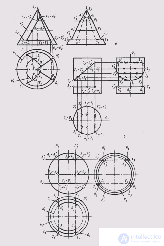
Fig. 130
In fig. 130, and construction of cut in the cylinder is shown. The cut is limited to three sides. The vertical face is bounded by two horizontal through edges 55 'and 66' and straight lines 5.6 and 5 '6' on the side surface of the cylinder. The inclined face is limited to the part of the ellipse on the lateral surface of the cylinder and the through edge 55 '. The horizontal face is a flat figure bounded by a part of a circle and a straight line 66 '.
The cut lines lying on the lateral surface of the cylinder are projected onto the base circumference on P 1 . Their profile projection is built on the points of measurement of their depths relative to the plane of symmetry of the cylinder f. Through edges 55 'and 66' are invisible on P 1 and P 3
In fig. 130, b shows the task of constructing a cut in a cone. The prismatic hole in the cone has three internal walls, the boundaries between which are the edges AA ', BE' and CC ', which are perpendicular to P2 i. The right wall (AE) has the shape of a trapezium, since the cutting plane of this wall passes through the vertex S and intersects the cone along the generators SD and SD '. Parts of these generators between points A (A ') and B (B 1 ) give the contour of the right wall. The bottom wall (between the edges BB ' and CC') is a part of a circle bounded parallel to h. The left wall (between the edges AA ' and CC') is bounded by a part of the parabola, the projections of which are defined by points F (P) on the cone's meridian and intermediate points K (K ') on the auxiliary parallel h'.
The profile meridian of the cone is “cut out” in the area between the points E (E ') and F (F).
In fig. 130, in constructed projections of a sphere with a notch. The prismatic hole has 4 internal walls, the boundaries between which are the edges AA ', BB', CC ', DD', which are perpendicular to P 2 .
Each wall is a part of a circle. The upper and lower parallel to P 1 and projected onto it as part of a circle with radii, which are determined by the parallels h and h '.
The equator is cut between points 1.5 and 2.6. The right and left walls of the cutout are parallel to П 3 and projected onto it as parts of a circle with radii defined by circles P and P '. The profile meridian is cut between points 3.7 and 4.8.
The given examples show that, by changing the position of the cutting planes, it is possible to get cuts of a given shape.

Comments
To leave a comment
10. Positional tasks
Terms: 10. Positional tasks