Lecture
A logic based agent is a special kind of stateful reflexing agent. In this agent, the results of perception become input data for a sequential logical circuit - a network of logical elements , each of which implements a logical connection, and registers, each of which stores the truth value of one statement. The outputs of this logic are registers corresponding to actions, for example, the output of Grab is true if the agent wants to grab something. If the entrance to the Glitter (shine) is directly connected to the exit of the Grab, then the agent grabs his target wherever he finds it.
Calculations of values using logic circuits are carried out according to the principle of processing the data flow : at each time interval, the values of the input data are set and signals are distributed through the logic circuit. Each time a logical element receives all the necessary data as an input, it produces a value at the output. This process is very similar to the process of direct inference in the column AND - OR, which is shown in the figure.
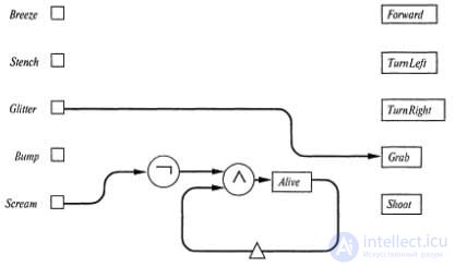
A part of the agent’s block diagram based on the logical scheme for the vampus world , which shows the inputs, outputs, the gold capture circuit, and the circuit for determining whether the vampus is alive. Registers are shown as rectangles, and one-step delays are indicated by small triangles.
In the previous section, it was pointed out that logic-based agents allow time relationships to be taken into account much more successfully than propositional logic-based agents. This is due to the fact that the value stored in each register shows the truth value of the corresponding propositional symbol at the current time t, therefore the register does not store separate copies of this value for each individual time interval.
For example, you can provide the register Alive, which must contain the value true if the vampus is alive, and false if it is dead. This register corresponds to the propositional symbol Alive t , therefore in each time interval it refers to different statements. The internal state of this agent (ie, its memory) is maintained by connecting the output of a certain register back to the same circuit through a delay line .
This allows you to deliver to the scheme information about the state of the register in the previous time interval. One example of such a construction is shown in the figure. The value of the register Alive is formed by the conjunction of the negation of perception of Scam and the value of the register Alive passed through the delay line. The action performed by this scheme in relation to the register Alive, can be represented in the form of statements as the following two-way implication:
Alive t <=> Scream t ^ Alive t -1
This statement means that a vampus is alive at a time t if and only if at the time t he did not hear his mournful death cry (such a state cannot be identified by a cry at time t-1), and he was alive at time t-1. It is assumed that when initializing this logic circuit, the value of the Alive register is set to true. Therefore, the value of the Alive register remains true until a vampus cry is heard, after which this value becomes false and remains so. This is exactly what is required.
The location of the agent can be monitored mainly using the same method by which we monitor the health of the vampus. This requires a separate register L x , y for each value of x and y; its value must be true if the agent is in the square [x, y]. However, the logic circuit that assigns the value to the L x , y register is much more complex than the logic circuit for the Alive register. For example, an agent is in the square [1,1] at time t, if, firstly, he was here at time t-1 and either did not move forward or tried to move, but hit the wall; secondly, it was in the square [1,2], looking down, and moved forward; thirdly, it was in the square [2,1], looking to the left, and moved forward. These three conditions can be described using the following statement:
L t 1,1 <=> (L t-1 1,1 ^ (¬Forward t-1 v Bump t )) v (L t-1 1,2 ^ (FacingDown t-1 ^ Forward t-1 )) v (Lt-12,1 ^ (FacingLeft t-1 ^ Forward t-1 ))
The circuit for register L 1,1 is shown in the figure. A similar circuit is connected to each location register. It is further proposed to design a logic for statements regarding orientation.
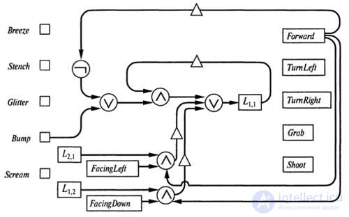
The scheme for determining whether the agent is squared [1,1]. A similar circuit is connected to each register with location and orientation.
The logic circuits shown in the figures constantly maintain the correct truth values for the registers Alive and L x , y . However, an unusual property of logical statements corresponding to these schemes and registers is that their correct truth values can always be checked. On the other hand, consider the statement B 4,4 that the breeze is felt in the square [4,4]. Despite the fact that the truth value of this statement remains constant, the agent will not be able to find out this truth value until he visits the square [4, 4] (or does not infer a logical way that there is a hole next to this square). The propositional logic and the logic of the first order are designed so that they can be used to automatically represent statements with true, false and unknown values, and the logic circuits do not have this property: the register for statements B4 / 4 must contain at least some value, or true or false, even though the true data about what its value is, have not yet been obtained. This means that the value in the register may well be wrong, and this will mislead the agent. In other words, the register must be represented by three possible states (the statement in 4/4 is obviously true, obviously false or of unknown meaning), but we have only one bit for this purpose.
The solution to this problem is to use two bits instead of one. Saying B 4,4 will be represented by two registers, which we will call K (B 4,4 ) and K (¬B 4,4 ), where K means "known". (Recall that these are still just characters with complex names, even though they look like structured expressions!) If both registers, K (B 4,4 ) and K (¬ B 4,4 ), contain a false value , then the truth value of B 4.4 is unknown. (And if both of them contain a true value, then there is an error in the knowledge base!) From now on, every time you need to use the statement B 4.4 in some part of the logic circuit, the statement K will be used instead (B 4,4 ), and when you need to use ¬B 4,4 , instead of it will serve K (¬B 4,4 ). Generally speaking, each potentially indefinite statement can be represented by two statements with a knowledge proposition (knowledge proposition), which make it possible to determine whether the corresponding statement is known to be true or known to be false.
Examples of how to use statements with the assessment of knowledge will be given shortly. But first it is necessary to carry out certain work in order to find a way to ascertain the truth values of the statements themselves with the assessment of knowledge. Note that the sentence B 4,4 has a constant truth value, and the values of the statements K (B 4,4 ) and K (¬B 4,4 ) change as the agent learns more about this world. For example, the statement K (B 4,4 ) is initially false, and then becomes true, as soon as it becomes possible to determine that the statement in 4/4 is true, i.e. after the agent goes into a square [4,4] and detects a breeze. Since then, it continues to be true. Thus, the following equation holds true:
K (B 4,4 ) t <=> K (B 4,4 ) t-1 v (L t4,4 ^ Breeze t )
A similar equation can be made for the statement K (¬B 4,4 ) t . Now, after the agent has found out in which squares the breeze is felt, he can go in to detect the pits. In the absence of a pit in a certain square, one can be sure if and only if it is known with respect to one of the neighboring squares that it does not feel a breeze. For example, the following equation holds:
K (¬P 4,4 ) t <=> K (¬B 3,4 ) t v K (¬B 4,3 ) t
The task of determining that there is a hole in a certain square is more difficult — for this, a breeze must be felt in one of the neighboring squares, which cannot be attributed to the presence of other wells, as the following equation shows:
Although the logic circuits for determining the presence or absence of pits are rather complex, with ^ = they contain only a constant number of logical elements per square. This property is essential if we are engaged in the creation of agents based on a logical scheme, designed to solve problems, the scale of which can be increased within reasonable limits. And in fact it is a property of the world of the vampus; An environment is called exhibiting the property of locality if the truth of each statement of interest to us can be determined by considering only a constant number of other statements.
The validity of the classification on the basis of locality very much depends on how accurately the “physical structure” of this environment is defined. For example, the domain for defining a game task in a minesweeper (Minesweeper) is non-local, since to find out if there is a mine in a given square, it may be necessary to check the squares that are at an arbitrary distance from it. Therefore, logic-based agents are not always practically applicable for non-local definition domains.
There remains one more problem that we have so far thoroughly avoided - the question of acyclicity . A logic circuit is acyclic if each path connecting the output of some register in the opposite direction to its input contains an intermediate delay element. We demand that all circuits be acyclic, since logic circuits that are cyclical do not work as physical devices! They can go into the mode of unstable oscillations, which leads to the appearance of uncertain values.
Additional clauses, K (¬B 3,4 ) t and K (¬B 4,3 ) t , allow the agent to determine whether the breeze is felt, based on known data on the presence of holes in the adjacent squares, and, at first glance, in this There is nothing wrong. But, unfortunately, the appearance of a breeze depends on the presence of pits in the adjacent squares, and the presence of pits depends on whether the breeze is felt in the adjacent squares, and this connection is established using equations similar to the equation. Therefore, a complete logic circuit will contain loops.
The difficulty here is not that the augmented equation has become wrong. Most likely, the problem is that intermediate dependencies represented by similar equations cannot be resolved by distributing truth values through the corresponding logic circuits. An acyclic version of a scheme constructed using an equation that determines the presence of breeze only through direct observation is incomplete in the sense that situations may arise where an agent based on a logic scheme is less knowledgeable than an agent based on inference using a complete inference procedure. For example, if a breeze is felt in a square [1,1], then an inference-based agent may conclude that a breeze is also felt in a square [2,2], and an acyclic logic-based agent using equation 7.6, for this not able to. The task of creating a complete logic circuit is feasible (after all, logic circuits make it possible to emulate any digital computer), but such a circuit will be much more complex than an acyclic logic circuit.
Comments
To leave a comment
Logics
Terms: Logics