Lecture
The approach based on the methodology of the general description and functional modeling of business processes is the IDEF0 methodology. It is based on the Integrated Computer-Aided Manufacturing (ICAM) methodology used in the US military aerospace laboratories in the development and creation of new types of aircraft and spacecraft. Later, on this basis, the US federal information technology standard was developed and introduced in 1993 - Publication? 183 (Federal Information Processing Standard, Publication 183).
Currently, this standard is the basis for the general functional description and modeling of various business processes and is used in many enterprises and organizations producing a wide variety of products and services.
IDEF0 is used to create a functional model that displays the structure and functions of the system, as well as the flow of information and material objects that are transformed by these functions.
The basis of the graphical language IDEF0, whose syntax and semantics are defined with absolute rigor, consists of blocks and arrows connecting them, which form a hierarchy of detailed diagrams.
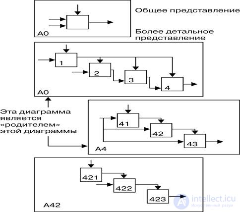
Figure 1. Hierarchy of detailed diagrams in IDEF0.
Blocks are some functions defined as activities, processes, or transformations. Their names fit into the frame of the block in the form of a verb phrase or a verbal noun. There is a clear hierarchical numbering of blocks, which always allows you to identify the location of each block in the total set of diagrams.
There are four types of arrows:
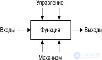
Figure 2. Positioning arrows in the IDEF0 model.
The components of the IDEF0 syntax are blocks, arrows, diagrams, and rules.
Blocks represent functions defined as an activity, process, operation, action, or transformation.
Arrows represent the data or material objects associated with the functions.
Rules define how components should be applied; diagrams provide a format for graphical and verbal description of models. The format forms the basis for managing the configuration of the model.
The block describes the function. Each block contains its name and number. The name must be a verb phrase or a verbal noun. The block number is located in the lower right corner. Block numbers are used to identify them in the diagram and in the corresponding text.
The arrow is formed from one or several straight line segments and a tip at one end. The arrow segments can be straight or broken; in the latter case, the horizontal and vertical segments of the arrow are mated by arcs having an angle of 90 °. Arrows do not represent a flow or sequence of events, as in traditional flowcharts or process flowcharts (flowcharts). They only show what data or material objects must be input to the function in order for this function to be performed.
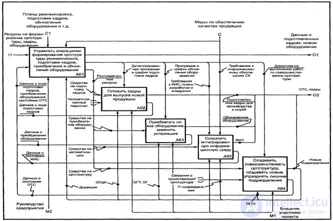
Figure 3. Arrows on the IDEF0 diagram.
The following syntax rules are set for blocks:
For arrows, the following syntax rules are set:
IDEF0 models consist of three types of documents:
These documents are cross-referenced to each other. A graphical diagram is the main component of the IDEF0 model, containing blocks, arrows, connections of blocks and arrows and their associated relations. The blocks represent the main functions of the simulated object. These functions can be broken down (decomposed) into its component parts and presented in the form of more detailed diagrams. The decomposition process continues until the object is described at the level of detail necessary to achieve the goals of a particular project.
Another IDEF0 concept is a glossary. For each of the IDEF0 elements: diagrams, blocks, arrows, the existing standard implies the creation and maintenance of a set of corresponding definitions, keywords, narrative presentations, etc., which characterize the object displayed by this element. This set is called a glossary and is a description of the essence of this element. The glossary harmoniously complements the visual graphic language, providing diagrams with the necessary additional information.
The top-level diagram provides the most general description of the simulation object. This chart is followed by a series of child diagrams that give a more detailed view of the object.
Each model must have a contextual top-level diagram in which the object of modeling is represented by a single block with boundary arrows. This diagram is called A – 0 (A minus zero). The arrows in this diagram represent the relationship of the object of modeling with the environment. Since a single block represents the entire object, its name is common to the entire project. The same is true for all diagram arrows, since they represent a complete set of object external interfaces. Diagram A – 0 sets the modeling area and its boundary.
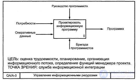
Figure 4. An example of a top-level contextual diagram.
Context diagram A – 0 should also contain brief statements defining the point of view of the official or department from the standpoint of which the model is created, and the goal for which it is being developed. The formulation of the goal expresses the reason for creating the model, that is, it contains a list of questions to which the model must answer, which largely determines its structure. The most important properties of an object are usually revealed at the top levels of the hierarchy; as the top level function decomposes and breaks it into subfunctions, these properties are refined. Each sub-function, in turn, is decomposed into elements of the next level, and this happens until a structure is obtained that allows answering the questions formulated in the purpose of the simulation. Each subfunction is modeled by a separate unit. Each parent block is described in detail by a child diagram at a lower level. All child diagrams must be within the scope of the top-level context diagram.
Often there are cases when individual arrows do not make sense to continue to consider in the child diagrams below a certain level in the hierarchy, or vice versa - individual blocks have no practical sense above a certain level. On the other hand, sometimes there is a need to get rid of individual “conceptual” shooters and not to detail them deeper than a certain level. To solve such problems, the concept of tunneling is provided in the IDEF0 standard. The designation of a “tunnel” in the form of two parentheses around the beginning of the arrow indicates that this arrow was not inherited from the functional parent block and appeared (from the “tunnel”) only on this diagram. In turn, the same designation around the end of the arrow in the immediate vicinity of the receiver unit means the fact that in the child diagram in relation to this unit this arrow will not be displayed and will not be considered. Most often, individual objects and the corresponding interface arrows are not considered at some intermediate levels of the hierarchy - in this case, they are first “plunged into the tunnel” and then, if necessary, “returned from the tunnel”.
The visibility of the graphical language IDEF0 makes the model quite readable for those who did not participate in the project of its creation, and also effective for holding shows and presentations. In the future, on the basis of the constructed model, new projects can be organized, aimed at producing changes in the enterprise (in the system).
When conducting complex enterprise survey projects, the development of models in the IDEF0 standard makes it possible to visually and efficiently display the entire mechanism of enterprise activity in the necessary section. However, the most important thing is the possibility of teamwork, which IDEF0 provides.

Comments
To leave a comment
Analysis and reengineering of business processes
Terms: Analysis and reengineering of business processes