Lecture
Many programmer tasks are conveniently solved using methods whose formalization can be tables of states and transitions (for example, their collection can be found in [32] and on the site http://is.ifmo.ru).
Example 9.1.1 . Model of the changing system.
Let us model a dynamic or ecological system, which has fundamentally different behavior in different areas. Instead of combining the analysis of which region the point belongs to, and calculating the next state of the system, we can write several simple modules for modeling the behavior of the system in each of the areas (the only test that may be necessary, we came out with next step of modeling outside the region or not). As a separate module, a global control program is built that checks the state of the system and calls the corresponding computing module.
In this case, the gain is not so much in the length of the program, as in its visibility and modifiability (although it is these very important qualities of the program that novice programmers most often underestimate). But if at the entrance to a new area you need to do a number of organizational actions (in each area are different), and depending on their result, choose a further trajectory of the system, then the description in the form of an automaton becomes more and more advantageous.
If, when analyzing a task, it is possible to identify a set of states of the process being described, conditions for transition between states and actions associated with states, then it is appropriate to solve the problem using the methods of state tables. When analyzing such methods, Moore finite automata can be used.
Theoretically, Moore's automaton is represented as a transition matrix, the rows of which are the states of the automaton, and the columns are the input symbols 1 . In practice, the input symbols can be considered the results of testing some conditions. Implicit in theory, but the most important in practice, the contents of each state of the automaton is a procedure leading to a global change in the state of the computational system. Such procedures are called actions .
Automata tables are often also presented as graphs , which is especially convenient when not all possible transitions between the two states are realizable. See, for example, fig. 9.1, where both the table and the graph are presented.
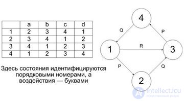
Here, states are identified by sequence numbers, and effects by letters.
On the state table or on its graph analogue, all actions are assumed to be global by default, and each action is connected to recognizing which of the conditions listed on the edges that go out of it is fulfilled. Depending on which of them is fulfilled, the automaton goes into the corresponding state, which again, if it is not final, is associated with the action and recognition.
There is a variation of the concept of automata, which generates another method of automaton programming. In theory, the Miles automaton is different in that the result recorded on the automaton output tape may depend on the selected transition. In practice, actions in the table of states and transitions can be associated either with states (with graph vertices, Moore’s automaton), or with transitions (with arcs of a graph, Mealy automaton). Below you will see examples when both of these 2 options naturally occur during programming. The Miles automaton computation model is better to use if the checks in each state are essentially different, and the Moore automaton model is if the checks are essentially homogeneous, as in Example 9.1.1. on transitions "), a method when actions are performed in states, we call transformations in states (abbreviated simply" in states ").
Note that it is natural to consider state and transition tables as non-deterministic, since after performing an action it may well be true that several conditions corresponding to outgoing edges may be true at once.
Attention !
In this case, we see one of the inexhaustible sources of errors in programs, which D. Gris first noted. If, in essence, the task doesn’t matter to us which of the actions will be performed, and the language (like the standard languages in which people usually work) forces the transitions to be determined, either by ranking them in order or by forcing their conditions to be logically inconsistent there are difficulties. They are connected with the fact that, after a change, it was necessary to determine something differently, but it is no longer possible to distinguish which of the conditions are significant and which are inserted only for determination .
As was shown in our example, transition and state tables are a natural way of programming for a module dealing with global operations on an environment (these global operations themselves are usually programmed in a different style). For automaton programming, go to is typical, and here it is in place.
There are many specific methods of automaton programming that fit into the framework of the two main methods. Automata programming well demonstrates how practical methods for solving logically and mathematically, seemingly homogeneous problems vary. A small change in resource constraints - and, although the old methods tend to remain relevant, it is better to move on to others.
The information space of all blocks and procedures for automaton programming in the first approximation is the same: the state of the system modeled by a set of program actions. But in fact, many blocks or procedures work with subsystems. Subsystems, due to their autonomy, may have characteristics that are directly inaccessible to the general system, and limited access to the total system data space. Moreover, the subsystems can communicate directly, bypassing the hierarchically superior system (see Figure 9.2). Thus, the structure of the information space with automaton programming in general corresponds to that imposed by modern systems with developed modularity 3 . In systems of modularity there are concepts provided for using other modules, there are modules that automatically gain access to all concepts of a friendly module, and there are interfaces between modules.
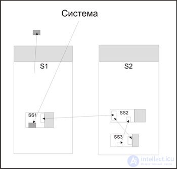
Light gray areas are the traditional overall context of a system and subsystem. Dark grays illustrate that accessibility can be one-way, and not only hierarchically. One of the systems can influence a part of the information space of the other, and the latter can only passively follow what a colleague has done. Areas connected by two-way arrows illustrate direct communication bypassing the hierarchy.
Historically, the first model of automaton programming, used both in practice and for theoretical studies, was the presentation of a program in the form of a flowchart (see, for example, Fig. 9.3), the nodes of which were states. The nodes of the flowchart are divided into five types:
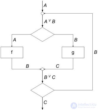
The representation of programs in the form of flowcharts was appropriate for many classes of programs that were written in machine codes without programming automation tools. The flowcharts were then the primary means of planning program development and documenting them. Traditional flowcharts are the subject of study, in particular, theoretical programming (see Kotov’s books [16], [17]).
Transition tables conceptually contradict such a fundamental notion of programming as assignment. In the block diagram of the arbitrary form, it is extremely difficult to trace how the value of a variable will change, what dependencies exist between these variables, and so on.
Actions in automaton programming are global, and conditions are local. Checking the condition does not change the state of the entire system (none of its parameters or characteristics), it only translates the program itself into one or another state.
This is confirmed by the analysis of practical systems for the simulation of which it is convenient to use automaton programming. For example, opening or closing one valve in a pipeline system changes all flows in the system, and checking whether the valve is open is a local operation. Changing the temperature of the working substance in the system again affects all its characteristics, and it is possible to measure this temperature by taking readings of just one sensor.
Here we are faced with the need to clearly distinguish between external concepts describing a system that is associated with a problem to be solved by a program, and internal concepts of the program itself. For the system as a whole, the states of the automaton that models it or interacts with it are indifferent. For her, it is important what changes in her happen. Thus, the state of the memory of a computing system can be quite regarded as an external characteristic with respect to the program that runs in it.
The need for simultaneous and coordinated consideration of external and internal characteristics leads to the fact that when internal characteristics are fragmented and detailed (for example, when the automaton programming style is combined with assignments), the programmer becomes confused, the consistency of concepts disappears and errors occur.
Attention !
If you use arbitrary tables of transitions, then you need to make sure that assignments are encountered as rarely as possible, ideally do without them completely, or assign only values to variables that are immediately used as a basis for selection in the operator type case .
The state and transition graph, also called the transition table, is a loaded directed graph G. A vertex is associated with each vertex of the graph G and a condition for each arc.
The condition AB associated with the arc leading from a to b is meaningfully interpreted as follows. When executing AB in state a, control is transferred to state b (or, in another sense, a transition is made along a given arc).
When the state and transition graph is used to document a program, the names of the states usually coincide with the names of the procedures that are executed in that state.
Note that the programmatic representations of the state graph strongly depend on the dynamics of a given graph. It is necessary to allocate four subcases.
In this section, a detailed demonstration of two methods of automaton programming based on the model of Moore and Mili begins. The method of working in them is almost the same, but, as is most often the case, a small and seemingly technical difference (to which actions are compared: states or transitions?) Generates two incompatible methods. Their incompatibility is not as gross as in many other cases (two such cases — incompatibility between automata and assignments and between cycles and recursions — are discussed below). If this is a contradiction, it is a technological contradiction. Randomly mixing these two methods, we further make it difficult to modify the program, and in the present we are forced to multiply the number of supports.
A person even ignores or ignores rough contradictions 4 . To apply the rule, it is important to know not only it, but also when it can be violated. The general methodological principle here is this: if we break, then to the fullest (having passed the intersection at a red light, it is foolish to stop right behind it)! The second principle: if it is impossible, but very necessary, then it is necessary! A. A. Shalyto pointed out that in theory 5 there is also such a mixed concept as Mili-Moore automata. One of the models of such automata is an automaton with two output tapes: on one the result is written in states, on the other - on transitions. The programmatic interpretation of such a theoretical model is, for example, a module that, in states, conducts a dialogue with the environment, as a result of which it receives data to determine the next transition, and performs internal calculations on the transitions.
To practice the technique, a simple task is used, which does not obscure its essence with particular subtleties and is suitable for implementation by either of the two methods. The resulting technique is transferred to a wide class of problems and does not fail up to thousands of states.
Suppose you want to solve the following problem. A word is any non-empty sequence of letters of the Latin alphabet (for simplicity, only lowercase letters). Reprint from the input sequence of characters all the maximum words in it in the following form:
-
Input ends with an empty string.
For example, in the lines
  hippo parrot
 1mot2krot1mot
need to issue something like
  parrot 7
 hippo 7
 Mot 3
 mole 4
 Mot 3
To solve a problem, it is natural to consider the input sequence of characters as a stream, readable from left to right, until an empty line is read. When reading letters, other characters and the end of a line, the actions that need to be performed are different. In addition, actions for the first letter and for subsequent letters of the word are distinguished.
First of all, we define a set of states based on different reactions to the read character.
Here is a complete list of reaction options:
There is one more action that is not reflected in this list, but implied: the standard action that takes place before the start of the development of a new state. In this case, it is the reading of the next character that should be performed when the transition is triggered. In other cases of automaton models, the role of reading the next character can play, say, the next modeling step. For this and for most other automaton examples, the standard action does not need to be specified explicitly, since it automatically matches each transition and fully corresponds to the mathematical model.
From the list of actions for the task in question it follows that there should be at least two classes of states that have different actions-reactions.
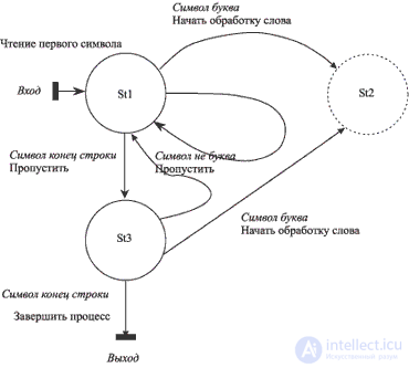
The next method is the determination of the initial state, i.e., the one in which the computational process is activated. You need to specify what actions are possible in this state and what conditions of transition in it should be.
For the case under consideration in the initial state ( St1 ), transitions are possible:
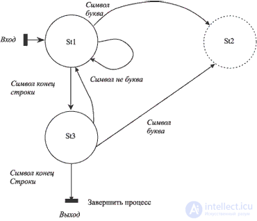
The result of the analysis just performed can be represented as a graph shown in Fig. 9.4. С каждой дугой графа связано условие перехода. С каждым состоянием может быть связано действие. В состояниях St1 и St3 действием является пропуск очередного символа и чтение следующего, но соединить их сейчас нельзя, поскольку в первом из них переход на завершение работы невозможен, так что перевод строки анализируется по-разному. Это позволяет предположить, что в данной задаче действия стоит ассоциировать спереходами, а не с состояниями. Правильный выбор того, с чем ассоциировать действия, может сильно оптимизировать программу. Для показа двух возможных вариантов, которые в данном случае почти эквивалентны по сложности, мы будем действовать как на переходах, так и в состояниях. В частности, предварительный анализ состояний при методе преобразований на переходах дан на рис. 9.5.
Attention !
Если у Вас есть две близкие, но концептуально противоречивые, модели, в начале развития программы нужно сделать выбор в пользу одной из них. Небольшие эксперименты и отступления в начале оборачиваются большой экономией сил в конце .
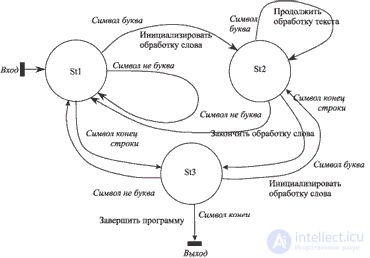
На схемах вход и выход обозначаются черными прямоугольными блоками. При желании их можно считать специальными состояниями, с которыми ассоциированы действия инициализации и завершения процесса. Состояние St2 изображено штриховой линией, поскольку анализего еще не проведен. Для каждого из еще не проанализированных состояний (в данном случае для St2 ) следует определить условияперехода (и соответствующие им действия, если выбрали работу на переходах ).
In this case, in the St2 state , transitions are possible:
After this construction, it is checked whether the new state is not a copy of the already existing ones both by actions and by transitions. If so, then the new state can be identified (glued) with one of the previously constructed. Newly appearing states are analyzed similarly.
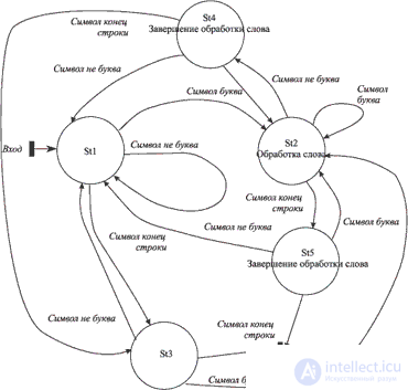
Для решаемой задачи легко выяснить, что состояние St3 требует тех же действий и переходов, что и St5 , а St4 изоморфно St1 . Следовательно, возможна склейка этих двух состояний со старыми и построение графа завершается, так как новых состояний нет (см. рис. 9.6). С тем, чтобы не дублировать действия <Завершить процесс>, можно определить еще одно, заключительное состояние, с выходом из которого будет ассоциировано это действие (один раз!).
Аналогично можно поступить и когда мы работаем в состояниях. Здесь процесс удлиняется на один шаг, поскольку необходимо выделить завершение обработки слова в отдельное действие (причем в двух вариантах: после перевода строки и после других небуквенных символов). Полученный результат показан на рис. 9.7.
Графическое или иное представление графа состояний конечного автомата, явно отражающее наименования состояний, условия переходовмежду состояниями и ассоциированные с ними действия, называют таблицей переходов . Такое представление является одним из центральных компонентов широко используемого в индустриальном программировании языка объектно-ориентированного дизайна UML (в частности, в форме, реализованной в системе Rational Rose ) - state transition diagrams (диаграммы состояний и переходов ).
Различают визуальные представления таблиц переходов, которые предназначены для человека, и их программные представления. Требования к визуальным представлениям - понятность для человека, статическая проверяемость свойств; требования к программным представлениям - выполнимость при посредстве какой-либо системы программирования; общее требование к представлениям обоих видов - однозначное соответствие между ними, позволяющее обоснованно утверждать вычислительную эквивалентность.
Ответ на вопрос, какое представление графа состояний лучше всего использовать, зависит от сложности графа, статичности либо динамичности его и того, для каких целей требуется спецификация в виде графа состояний. Понятно, что важнейшей для нас промежуточной целью является программа на алгоритмическом языке. Но подходы к построению такой программы могут быть различны. Существует две принципиально различные методики применения спецификаций:
Как при трансляционной, так и интерпретационной позиции возможен целый спектр реализаций. Ближайшая же цель в том, чтобы научиться удобно для человека представлять граф состояний и переходов. Наиболее естественно описывать его в виде таблицы. Для методов на переходах и в состояниях таблицы несколько различаются. На табл. 9.1 представлен случай Мили. Опишем значение колонок таблицы.
Кроме того, определяется специальная (первая) строка, в которой помещаются операторы, инициирующие процесс, и адрес переходаначального состояния.
В табличном представлении графа переходов в состояниях (таблица 9.2) действия помещаются во втором столбце, сразу после обозначениясостояния, а уже затем идут переходы. Анализируя таблицу 9.2, можно заметить ряд повторяющихся действий. Конечно же, если бы эти действия были более сложными, их просто описали бы как процедуры. Но такие повторения заставляют задуматься, а нельзя ли сократить число состояний? Введя дополнительную булевскую переменную, отметившую, что последним символом был перевод строки, мы могли бы избавиться от пары состояний. Но такой переменной нужно присваивать новое значение в процессе проверки условий, и при этом в строго определенный момент: сначала проверить, не является ли символ концом строки, а уже затем переприсваивать данную переменную. Это решение сильно отдает хакерством, и, если Вы хотите писать качественные, легко перестраиваемые программы, то таких решений нужно избегать.
Еще раз показать тонкую грань между хакерством и естественностью можно, рассмотрев один из моментов, возникающих в наших программах. При работе в состояниях нам приходится обнулять счетчик букв слова в тот момент, когда кончается очередное слово, поскольку иначе пришлось бы выделять еще одно состояние, соответствующее середине обработки слова. Но это гораздо менее искусственное решение: неплохо восстанавливать начальные значения и делать другие действия по приведению в порядок информации в тот момент, когда заканчивается очередной этап работы; неплохо делать это всегда в начале нового этапа; плохо лишь произвольно перемешивать эти две дисциплины.
|
char symbol; // Чтение потока символов неявное // Чтение происходит перед выполнением проверок и действий int Cnt; . . . // Инициализация |
St1 | ||
|---|---|---|---|
| St1 | 'a'<=symbol && symbol <= 'z' | printf ("%c", symbol); Cnt = 1; | St2 |
| /*(symbol<'a'|| 'z' | /* Действий нет */ | St1 | |
| symbol='\n' | /* Действий нет */ | St3 | |
| St2 | 'a'<=symbol && symbol <= 'z' | printf ("%c", symbol);cnt++; | St2 |
| /*(symbol<'a'|| 'z' | printf ("- %i\n", Cnt); | St1 | |
| symbol='\n' | printf ("- %i\n", Cnt); | St3 | |
| St3 | 'a'<=symbol && symbol <= 'z' | printf ("%c", symbol); Cnt = 1; | St2 |
| /*(symbol<'a'|| 'z' | /* Действий нет */ | St1 | |
| symbol='\n' | Второй '\n' дальше не нужно читать | exit | |
| exit | /* Нет неявного чтения потока */ | return 0; // Consider this section of the table as a state or not - a matter of taste | |
|
char symbol; // Reading implicit character stream // Reading occurs after performing the action, before checking int Cnt; ... Cnt = 0; // Initialization |
St1 | ||
|---|---|---|---|
| St1 | / * No action * / | 'a' <= symbol && symbol <= 'z' | St2 |
| / * (symbol <'a' || 'z' | St1 | ||
| symbol = '\ n' | St3 | ||
| St2 | printf ("% c", symbol); Cnt ++; | 'a' <= symbol && symbol <= 'z' | St2 |
| / * (symbol <'a' || 'z' | St4 | ||
| symbol = '\ n' | St5 | ||
| St3 | / * No action * / | 'a' <= symbol && symbol <= 'z' | St2 |
| / * (symbol <'a' || 'z' | St1 | ||
| The second '\ n' no longer needs to read symbol = '\ n' | exit | ||
| St4 | printf ("-% i \ n", Cnt); Cnt = 0; | 'a' <= symbol && symbol <= 'z' | St2 |
| / * (symbol <'a' || 'z' | St1 | ||
| symbol = '\ n' | St3 | ||
| St5 | printf ("-% i \ n", Cnt); Cnt = 0; | 'a' <= symbol && symbol <= 'z' | St2 |
| / * (symbol <'a' || 'z' | exit | ||
| The second '\ n' no longer needs to read symbol = '\ n' | exit | ||
| exit | / * No implicit stream reading * / | return 0; // Consider this section of the table as a state or not - a matter of taste | |

Comments
To leave a comment
Programming Styles and Techniques
Terms: Programming Styles and Techniques